Cable connector

A technology of cable connectors and cable cores, applied in the direction of insulated cables, cables, circuits, etc., can solve the problems of affecting the service life of cables, insufficient mechanical tensile strength, and easy deformation, etc., to increase mechanical tensile strength and improve recovery The effect of strength and prolonging the safety of use

Inactive Publication Date: 2019-11-22
邓超
View PDF0 Cites 0 Cited by
  • Summary
  • Abstract
  • Description
  • Claims
  • Application Information

AI Technical Summary

Problems solved by technology

[0004] At present, the mechanical tensile strength of the cable connector is not enough when charging the car. When the car starts suddenly, it is easy to cause the cable to break, and when the cable is squeezed, it is easy to deform, which affects the service life of the cable.

Method used


Image

  • Cable connector

Examples


Embodiment Construction

[0013] In order to make the object, technical solution and advantages of the present invention clearer, the present invention will be further described in detail below in conjunction with the accompanying drawings and embodiments. It should be understood that the specific embodiments described here are only used to explain the present invention, not to limit the present invention.

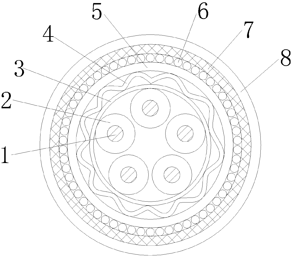
[0014] see figure 1 , figure 1 It is a structural schematic diagram of the present invention.

[0015] A cable connector, comprising a cable core 1 composed of a plurality of copper wires and an outer insulating sheath 8, the outer surface of each cable core 1 is provided with an inner insulating sheath 2, and the outer surface of the inner insulating sheath 2 A cable wrapping 3 is provided, and between the outer side of the cable wrapping 3 and the outer insulating sheath 8, a return spring plate 4, a polyvinyl chloride sheath 5, a copper wire armor layer 6 and a spring weaving net 7 are sequent...


PUM

PropertyMeasurementUnit
thicknessaaaaaaaaaa

Abstract

The invention relates to a cable connector. A cable used for the cable connector comprises the cable cores composed of a plurality of copper wires and an outer insulating sheath, an inner insulating sleeve is arranged on the outer side surface of each cable core, and a cable wrapping tape is arranged at the outer side of the inner insulating sleeve; a return spring plate, a polyvinyl chloride sleeve, a copper wire armor layer and a spring weaving net are sequentially arranged between the outer side of the cable wrapping tape and the outer insulating sheath, and the return spring plate, the polyvinyl chloride sleeve, the copper wire armor layer and the spring weaving net are fixedly connected. By arranging the return spring plate, the return force of the cable can be effectively improved under the action of the return spring plate, and the cable can be conveniently and quickly returned; by arranging the polyvinyl chloride sleeve, the copper wire armored layer and the spring weaving net,the mechanical tensile strength of the cable during the construction process can be effectively improved under the action of the polyvinyl chloride sleeve, the copper wire armor layer and the springweaving net, the use safety of the cable is improved, and the normal work of the equipment is ensured.

Description

technical field [0001] The invention relates to the technical field of cables, in particular to a cable connector. Background technique [0002] The function of the charging pile is similar to the refueling machine in the gas station. It can be fixed on the ground or wall, and installed in public buildings (public buildings, shopping malls, public parking lots, etc.) and residential area parking lots or charging stations. Charge all models of electric vehicles. The input end of the charging pile is directly connected to the AC grid, and the output end is equipped with a charging plug for charging the electric vehicle. Charging piles generally provide two charging methods: conventional charging and fast charging. People can use a specific charging card to swipe the card on the human-computer interaction interface provided by the charging pile to perform corresponding charging methods, charging time, and cost data printing. The display screen of the charging pile can display...

Claims


Application Information

Patent Timeline
Patent Type & Authority Applications(China)
IPC IPC(8): H01B7/18H01B7/22
CPCH01B7/18H01B7/22
Inventor 邓超
Owner 邓超
Why Eureka
Try Eureka