
Optical scanning module and manufacturing method thereof

An optical scanning and module technology, applied in electrical components, electrical solid devices, circuits, etc., can solve problems such as poor response speed and poor heat dissipation performance, improve service life, improve heat dissipation performance, and overcome excessive welding lead resistance. Effect

Pending Publication Date: 2019-11-22
纮华电子科技(上海)有限公司
View PDF0 Cites 0 Cited by
  • Summary
  • Abstract
  • Description
  • Claims
  • Application Information

AI Technical Summary

Problems solved by technology

[0007] The object of the present invention is to provide an optical scanning module and its manufacturing method to solve the problems of poor heat dissipation performance and poor response speed

Method used


Image

  • Optical scanning module and manufacturing method thereof
  • Optical scanning module and manufacturing method thereof
  • Optical scanning module and manufacturing method thereof

Examples


Embodiment Construction

[0034] The present invention is described in detail below in conjunction with accompanying drawing:

[0035] Please refer to Figure 6 to Figure 15, the optical scanning module 100 provided by the embodiment of the present invention includes an optical sensor 140, an electronic component 160, a heat sink substrate 110, a heat conduction bracket 120, and an optical lens 130 sequentially connected from bottom to top, and the lower plane of the heat conduction bracket 120 A groove 121 is arranged upward, and a light-transmitting groove 122 is also arranged on the heat sink substrate 110 . The upper plane of the groove 121, the optical sensor 140 is also in contact with the heat sink substrate 110 through the heat conduction medium layer 170, the electronic components 160 are arranged on the heat sink substrate 110, and the electronic components 160 is located in the orthographic projection area of ​​the groove 121 and staggered distribution with the light sensor 140, the pad of ...


PUM


Abstract

The invention provides an optical scanning module and a manufacturing method thereof. The optical scanning module comprises an optical sensor, an electronic component, a heat sink substrate, a heat conduction support and an optical lens, wherein the heat sink substrate, the heat conduction support and the optical lens are connected in order from bottom to top; a groove is upwards formed in the lower plane of the heat conduction support; the heat sink substrate is also provided with a light-transmitting groove; the groove is communicated with a light transmitting groove; an optical sensor is welded to the upper plane of the groove in an inverted mode through a solder ball; the optical sensor is also in contact connection with the heat sink substrate through a heat-conducting medium layer; the electronic component is located in the orthographic projection area of the groove and is staggered with the optical sensor; a bonding pad of the heat conduction support is in circuit connection with a bonding pad of the heat sink substrate; and light passing through the optical lens penetrates through the light transmitting groove and can irradiate the optical sensor. The heat dissipation performance and the reaction speed can be improved.

Description

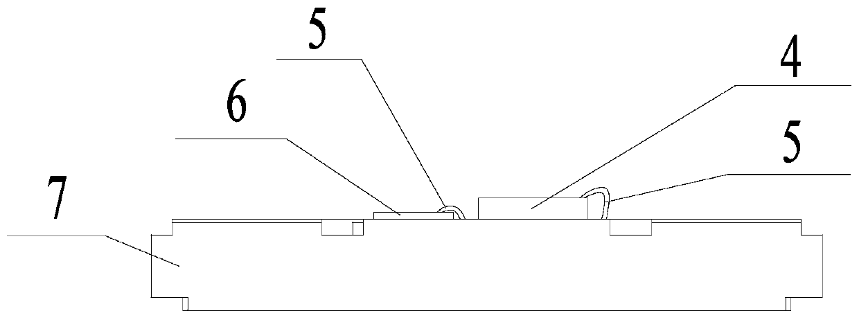
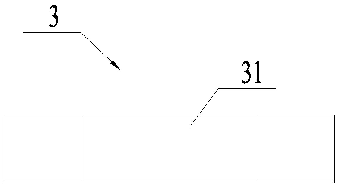
technical field [0001] The invention relates to the field of optoelectronic technology, in particular to an optical scanning module and a manufacturing method thereof. Background technique [0002] 3D optical scanning module and other optical scanning modules are used for face recognition, gesture recognition, 3D reconstruction and 3D structured light scanning modeling. The 3D optical scanning module can be applied to mobile phones, tablet computers, notebook computers and desktop computers. For example, AR or VR applications of mobile phones, etc. Please refer to Figure 5 , the 3D optical scanning module in the prior art includes a heat sink substrate 7, which is attached to the photodiode 6 and 3D light sensor 4 in a staggered distribution on the heat sink substrate 7, and is located on the heat sink substrate 7 and exposes the photodiode 6 and 3D photosensor 4. The bracket 3 of the light sensor 4 and the optical filter 1 fixed on the bracket 3 by glue 2 . Wherein the ...

Claims


Application Information

Patent Timeline
Patent Type & Authority Applications(China)
IPC IPC(8): H01L25/16H01L23/055
CPCH01L25/167H01L23/055
Inventor 杨孝东
Owner 纮华电子科技(上海)有限公司
Learn More