
Method for producing multilayer fiber composite preform for fiber composite component

一种纤维复合、多层纤维的技术,应用在纺织品和造纸、编织物等方向,能够解决废品、妨碍纤维复合构件几何和机械性能以及光学外观等问题,达到简单措施、制造改善、低成本的效果

Active Publication Date: 2019-11-22
BAYERISCHE MOTOREN WERKE AG
View PDF8 Cites 1 Cited by
  • Summary
  • Abstract
  • Description
  • Claims
  • Application Information

AI Technical Summary

Problems solved by technology

Such differences negatively impair the geometric and mechanical properties as well as the optical appearance of the finished fiber composite components and can even lead to scrap

Method used


Image

  • Method for producing multilayer fiber composite preform for fiber composite component
  • Method for producing multilayer fiber composite preform for fiber composite component
  • Method for producing multilayer fiber composite preform for fiber composite component

Examples


Embodiment Construction

[0034] Components with the same function and mode of action are in the Figures 1 to 3 Correspondingly provided with the same reference numerals.

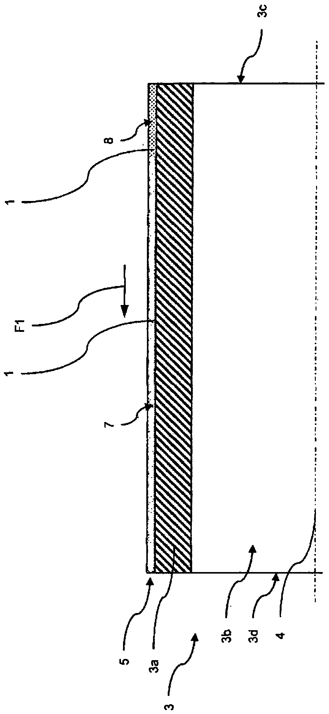
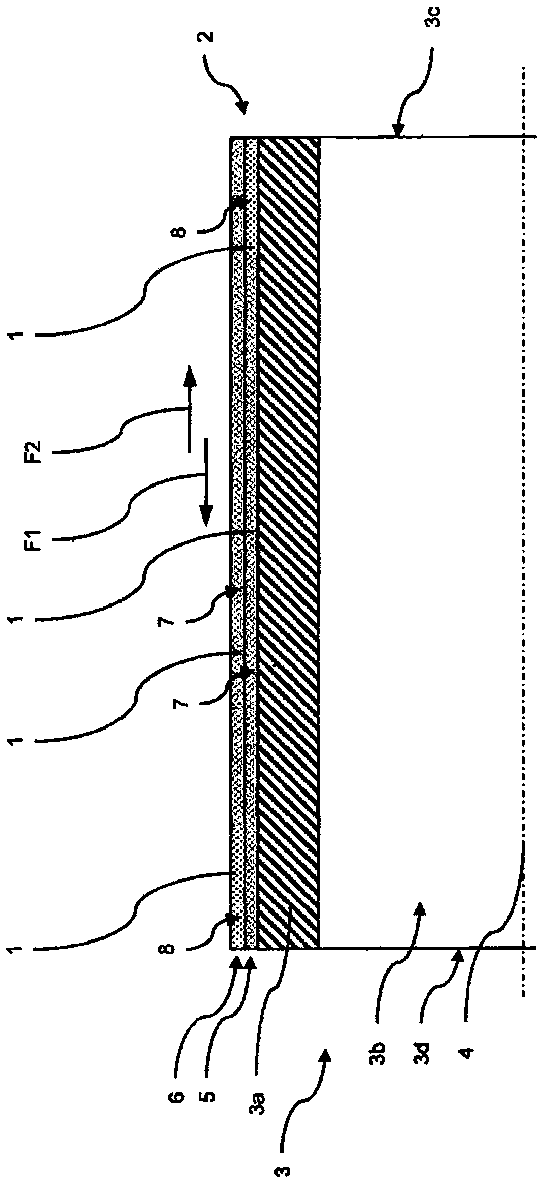
[0035] figure 1 A section of the support core 3 covered with the first textile layer 5 is schematically shown in a side view. The support core 3 is designed rotationally symmetrically about the support core longitudinal axis 4 and has a surrounding support core wall 3 a which radially surrounds the support core cavity 3 b. On the outer side of the support core 3 facing away from the support core longitudinal axis 4 , or on the support core wall 3 a, a first fabric layer 5 made of fiber rovings 5 ​​is arranged. By means of the method according to the invention, said first fabric layer 5 is produced from a first support core end 3c in a first weaving direction F1 towards a second support core end 3d.

[0036] The first textile layer 5 has a region of low textile density 8 on the first support core end 3c and a region of high texti...


PUM


Abstract

The invention relates to a method for producing a fiber composite preform (2) for a fiber composite component, said fiber composite preform having a plurality of layers of a fiber roving (1). The method comprises the following steps: providing a supporting core (3) for arranging the fiber rovings (1) on a braiding device, the supporting core (3) having a supporting core longitudinal axis (4), producing a first braided fabric layer (5) from fiber rovings (1) on the supporting core (3) in a first braiding direction (F1) parallel to the supporting core longitudinal axis (4) of the supporting core(3) by means of the braiding device, and producing a second braided fabric layer (6) from fiber rovings (1) on the first braided fabric layer (5) by means of the braiding device. According to the invention, the second braided fabric layer (6) is produced in a second braiding direction (F2) parallel to the supporting core longitudinal axis (4), the second braiding direction (F2) being opposite thefirst braiding direction (F1).

Description

technical field [0001] The invention relates to a method for producing a fiber composite preform having multiple layers of fiber rovings for fiber composite components, in particular for motor vehicles. Background technique [0002] Reducing the gross vehicle weight is increasingly important to the manufacture of motor vehicles. One reason for this is that reducing overall weight is directly linked to improved driving dynamics, reduced fuel consumption and reduced emissions. This correlation is based in particular on the laws of inertial physics, according to which a force proportional to the mass is required in order to accelerate it with a given acceleration. A reduction in vehicle mass, eg by replacing components with lighter components, therefore means that less driving force is required to achieve a given acceleration. [0003] One known process for reducing vehicle weight is the use of lighter materials configured to produce components with lower component weights an...

Claims


Application Information

Patent Timeline
Patent Type & Authority Applications(China)
IPC IPC(8): D04C1/04B29B11/16D04C3/12
CPCB29B11/16D04C1/04D04C3/12D10B2505/02D10B2101/12
Inventor M·迪克曼F·拉普
Owner BAYERISCHE MOTOREN WERKE AG
Learn More