Eureka AIR delivers breakthrough ideas for toughest innovation challenges, trusted by R&D personnel around the world.

Rotary table boring rotation error measuring and compensating method

A technology of rotary error and compensation method, which is applied in the direction of measuring/indicating equipment, other manufacturing equipment/tools, metal processing machinery parts, etc., and can solve problems such as poor compensation accuracy and affecting the accuracy of the error measurement value of the rotary system of the turntable

Active Publication Date: 2019-11-26
XIAN FLIGHT SELF CONTROL INST OF AVIC
View PDF5 Cites 3 Cited by
  • Summary
  • Abstract
  • Description
  • Claims
  • Application Information

AI Technical Summary

Problems solved by technology

Due to the limitation of the processing method of the existing rotary alignment body, the cylindricity error of the alignment hole is about 0.004mm, and the error of the generatrix of the alignment hole is about 0.003mm. These two errors are random errors, which are mixed in the turntable after accumulation. In the measured value of the error of the rotary system, it affects the accuracy of the measured value of the error of the rotary system of the turntable
In addition, the existing compensation uses the error value of the rotary system of the turntable in a certain direction as the error value of the rotary system in all directions of the turntable for compensation, and the compensation accuracy is poor.

Method used


Image

  • Rotary table boring rotation error measuring and compensating method
  • Rotary table boring rotation error measuring and compensating method
  • Rotary table boring rotation error measuring and compensating method

Examples


Embodiment 1

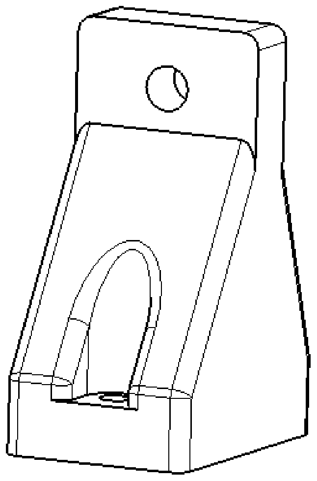
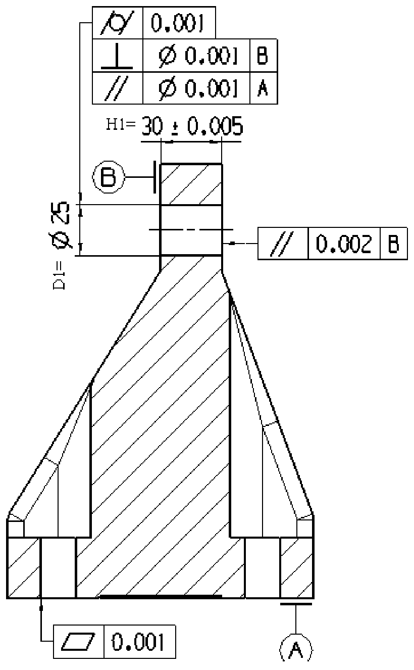
[0026] figure 1 It is a structural schematic diagram of the rotary aligning body of the present invention, figure 2 It is a sectional view of the rotary aligning body of the present invention, as figure 1 with figure 2 As shown, the diameter D1 of the alignment hole is φ25mm, the hole depth H1 is 30±0.005mm, the cylindricity is 0.001mm, the perpendicularity between the alignment hole and the end surface B is 0.001mm, and the parallelism between the two end surfaces B is 0.002 mm. After the rotary aligning body is made, it can be used repeatedly for a long time without loss of accuracy and function.

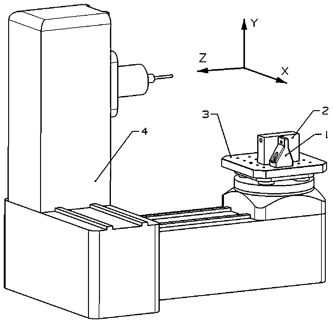
[0027] image 3 It is a schematic diagram of the installation of the rotary aligning body and the processed parts on the machine tool of the present invention. Press the rotary alignment body 1 image 3 As shown, it is fixed on the turntable 3 of the machine tool. Use a dial gauge to straighten the surface B of the rotary alignment body within 0.001mm, straighten the surfa...


PUM


Abstract

The invention belongs to the technical field of hole-series machining, and particularly relates to a rotary table boring rotation error measuring and compensating method which precisely compensates rotary table rotary system errors while a machine tool rotary table rotates by 180 degrees, and the two ends of the machine tool rotary table are bored. The rotary table boring rotation error measuringand compensating method comprises the following steps: designing a rotary aligning body, measuring rotary table rotary system errors, compensating the rotary table rotary system errors, and processingworkpieces. The rotary table boring rotation error measuring and compensating method can precisely measure an error value of the rotary table rotary system, and precisely compensates the rotary tablerotary system errors while the two ends of the workpieces are bored.

Description

technical field [0001] The invention belongs to the technical field of hole system machining, and in particular relates to a method for accurately measuring and compensating the rotation error of boreholes at both ends of a machine tool turntable rotating 180°. Background technique [0002] Boring is a common hole processing method in mechanical cutting. Boring at both ends is one of the methods of boring. It is mainly used in the precision machining of elongated holes with relatively large length and diameter. In boring processing, if the overhang of the boring bar is too long, the rigidity of the entire boring system will be reduced, and the end of the tool will vibrate, which will affect the machining accuracy of the boring. Therefore, in the processing of elongated holes with relatively large long diameters, the rotary table of the machine tool (hereinafter referred to as the turntable) is usually rotated 180°, and the tools are bored from both ends of the same hole of t...

Claims


Application Information

Patent Timeline
Patent Type & Authority Applications(China)
IPC IPC(8): B23Q17/22B23Q23/00
CPCB23Q17/22B23Q23/00
Inventor 何永红曹雅维袁甲
Owner XIAN FLIGHT SELF CONTROL INST OF AVIC
Why Eureka
Eureka Blog
Learn More