Construction method of air duct structure sharing side wall together with subway station

A technology for subway stations and construction methods, which is applied in the direction of infrastructure engineering, underwater structures, artificial islands, etc., and can solve the problems of narrow gaps between shared side walls and station enclosure piles, little impact of cross operations, and inability to install formwork, etc. It achieves the effects of avoiding foundation pit instability accidents, having little impact on cross-operation, and reducing the amount of demolishing works

Pending Publication Date: 2019-11-26
URBAN MASS TRANSIT ENG CO LTD OF CHINA RAILWAY 11TH BUREAU GRP
View PDF0 Cites 3 Cited by
  • Summary
  • Abstract
  • Description
  • Claims
  • Application Information

AI Technical Summary

Problems solved by technology

[0004] According to the deficiencies of the prior art, the present invention provides a construction method for an air duct structure that shares a side wall with a subway station. The construction method can solve the problem that the gap between the shared side wall and the station surrounding piles is too narrow to install formwork and affect the construction of the side w

Method used


Image

  • Construction method of air duct structure sharing side wall together with subway station
  • Construction method of air duct structure sharing side wall together with subway station
  • Construction method of air duct structure sharing side wall together with subway station

Examples


Embodiment Construction

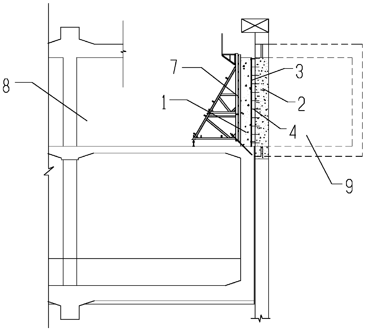
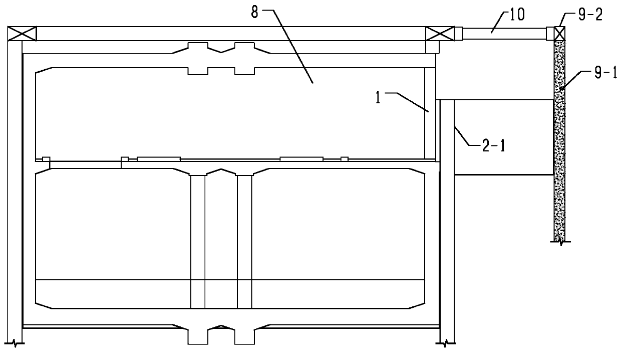
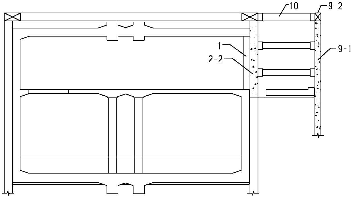
[0035] The present invention will be further described below in conjunction with the embodiments and accompanying drawings. attached Figure 1 to Figure 12 All are drawings of embodiments of the present invention, drawn in a simplified manner, and are only used for the purpose of clearly and concisely illustrating the embodiments of the present invention. The following technical solutions shown in the drawings are specific solutions of the embodiments of the present invention, and are not intended to limit the scope of the claimed invention.

[0036] In the following embodiments, it should be understood that the orientations or positional relationships indicated by the terms "upper", "lower", "inner", "outer", "left", "right" etc. are based on the orientations shown in the drawings Or positional relationship, or the orientation or positional relationship that is usually placed when the product of the invention is used, or the orientation or positional relationship that is com...


PUM

PropertyMeasurementUnit
Diameteraaaaaaaaaa
Widthaaaaaaaaaa

Abstract

The invention provides a construction method of an air duct structure sharing a side wall together with a subway station. The construction method of the air duct structure sharing the side wall together with the subway station specifically comprises the steps of firstly, adopting a mode of erecting templates on the two sides to construct the side wall shared by the air duct structure and the subway station; secondly, breaking station fender posts in a shared side wall area according to a mode of breaking one post every 2-4 posts; finishing excavation of earthwork and construction of an air duct bottom plate, wherein the air duct bottom plate is connected with a station middle plate through a fender post breaking area to form a temporary support; after a station main body structure is constructed, breaking the rest fender posts, and pouring micro-expansion concrete in the breaking area; and fixing the template on the air duct side of the shared side wall on a supporting net sheet by embedding a steel reinforcement anchor bolt in the station building envelope and welding the supporting net sheet on the exposed end of the steel reinforcement anchor bolt. The construction method of theair duct structure sharing the side wall together with the subway station can be widely used for construction of the air duct structure when the station and an air duct share the side wall; the apparent mass of concrete of a shared side wall cast-in-place structure is guaranteed; and the occurrence of foundation pit instability accidents is avoided.

Description

technical field [0001] The invention relates to the construction field of a main structure of an air duct of a subway station, in particular to a method for constructing an air duct structure when the station enclosure piles and side walls are shared with the air duct. Background technique [0002] At present, most of the urban underground rail stations and their auxiliary air duct structures are constructed in stages. The side walls of the air duct structure and the surrounding piles of the foundation pit are set separately from the subway station. The retaining piles are used to play the function of the air duct structure; the space position of the surrounding retaining piles and side walls of individual urban auxiliary structures adopts an intensive design method, that is, the side walls of the subway station and the side walls of the air duct structure are shared. The construction process of this scheme is cumbersome, and there are many cross-operations of various types ...

Claims


Application Information

Patent Timeline
IPC IPC(8): E02D29/045E04B1/00E04F17/04
CPCE02D29/045E02D2250/0007E02D2300/002E02D2600/30E04B1/0007E04F17/04
Inventor 解元元陆国平宋鹏飞谭敬村陈钦朱明喜李飞鹏
Owner URBAN MASS TRANSIT ENG CO LTD OF CHINA RAILWAY 11TH BUREAU GRP
Why Eureka
Try Eureka