A single-side glass reinforcement-reinforcement cage structure for the ground connection wall of the shield tunnel

A ground-connected wall and reinforcement cage technology, which is applied to structural elements, underwater structures, and infrastructure engineering, can solve the problems of glass fiber reinforcement cages that cannot be hoisted, long hoisting time, and tank wall collapse, etc., to reduce engineering costs. Quantity, save hoisting time, ensure the effect of bending resistance

Active Publication Date: 2021-02-02
CHINA TIESIJU CIVIL ENG GRP CO LTD
View PDF8 Cites 0 Cited by
  • Summary
  • Abstract
  • Description
  • Claims
  • Application Information

AI Technical Summary

Problems solved by technology

At the opening of the 1.5m-thick underground diaphragm wall, double-sided glass bars with equal cross-sections may be used. During the hoisting process, the glass fiber cage may not be hoisted, or the steel bars on both sides may be squeezed toward the glass fiber cage, causing the glass fiber bars to be broken. Therefore, the fiberglass cage needs to be reinforced with steel bars or channel steel alone. During the process of lowering the reinforcement cage, the reinforced steel bars or channel steel need to be cut off, which is time-consuming and may cause construction risks such as the collapse of the tank wall and serious shrinkage cavities due to too long hoisting time.

Method used


Image

  • A single-side glass reinforcement-reinforcement cage structure for the ground connection wall of the shield tunnel
  • A single-side glass reinforcement-reinforcement cage structure for the ground connection wall of the shield tunnel
  • A single-side glass reinforcement-reinforcement cage structure for the ground connection wall of the shield tunnel

Examples


Embodiment Construction

[0027] Hereinafter, the present invention will be described in detail with reference to the accompanying drawings. It should be noted that, in the case of no conflict, the embodiments in the present application and the features in the embodiments can be combined with each other.

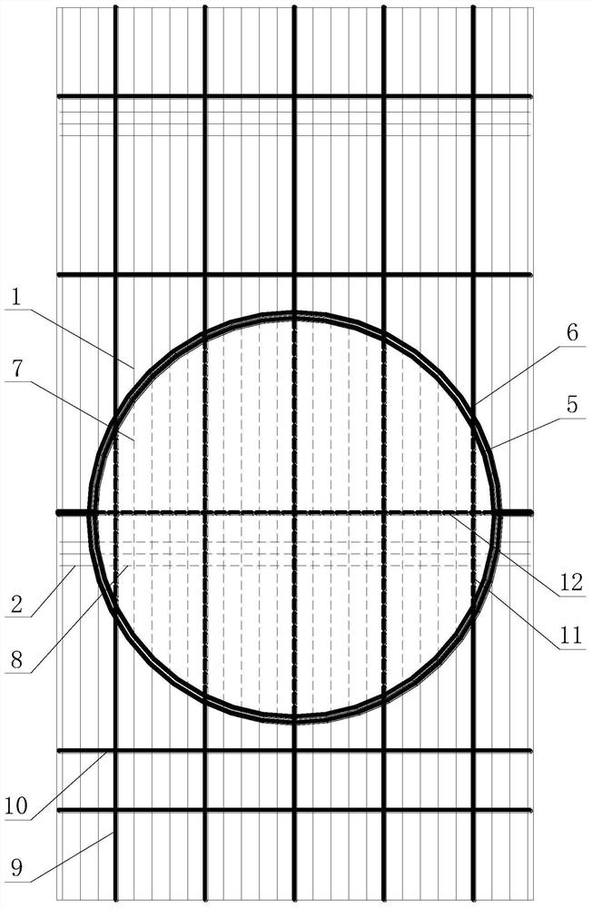
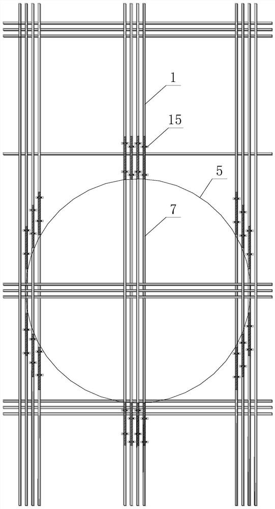
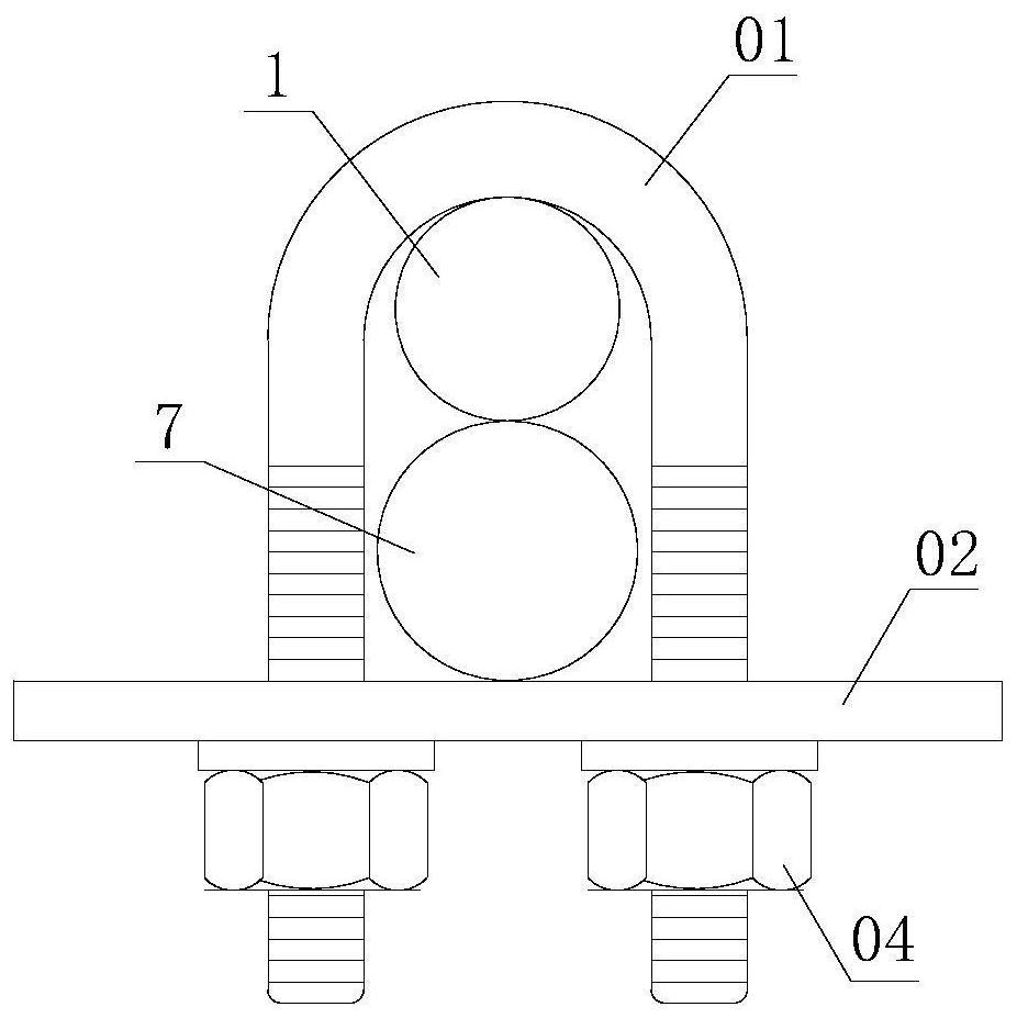
[0028] see Figure 1 to Figure 7 .

[0029] The invention is used for the single-side glass reinforcement-reinforcement cage structure of the ground connection wall of the shield tunnel door, including the ground connection wall reinforcement cage. Side vertical steel bars 1 and a plurality of soil-facing horizontal steel bars 2 arranged in the vertical direction, the back soil side of the ground connection wall reinforcement cage is closely connected with a door steel ring 5, and the ground connection wall reinforcement cage A circular steel bar truss 6 arranged coaxially with the door steel ring 5 is connected between the soil facing side and the back soil side, and the circular steel bar truss 6...


PUM


Abstract

The invention discloses a unilateral glass rib-reinforcement cage structure for a shield tunnel portal diaphragm wall. The structure comprises an underground diaphragm wall reinforcement cage, a tunnel portal steel ring is tightly attached to and connected to the soil backing side face of the underground diaphragm wall reinforcement cage, an annular reinforcement truss which is concentric with thetunnel portal steel ring is connected between a soil facing side face and a soil backing side face of the underground diaphragm wall reinforcement cage, the annular reinforcement truss is located onthe periphery of the tunnel portal steel ring, the parts, located on the inner periphery of the tunnel portal steel ring, of soil facing side vertical reinforcements striding over the tunnel portal steel ring are replaced by vertical glass fiber bars, and the parts, located on the inner periphery of the tunnel portal steel ring, of soil facing side horizontal reinforcements striding over the tunnel portal steel ring are replaced by horizontal glass fiber bars. The tunnel portal steel ring is used for receiving and pre-burying a shield tunneling machine when serving as a main body structure, and the arranged annular reinforcement truss is used for ensuring that the glass fiber bars are not influenced by gravity to be infinitely broken when the reinforcement cage is lifted, so that the lifting safety of the reinforcement cage can be ensured, and the stress requirement of a wall body can be met.

Description

technical field [0001] The invention relates to the field of subway construction, in particular to a single-side glass reinforcement-reinforcement cage structure used for ground connection walls of shield tunnels. Background technique [0002] Conventional subway stations usually have two floors, and triple-pipe high-pressure piles are usually used for reinforcement at the ends. The demolition of the portal is the overall demolition of the enclosure within the portal, and the safety risk is small. For ultra-deep transfer stations (three to four floors) that are adjacent to surrounding buildings or affected by underground structures, there is no ground reinforcement condition, and there is high pressure water under the basement. Conventional horizontal reinforcement and freezing method reinforcement cannot meet the construction safety of opening doors Requirements; There are still certain construction risks when demolishing the portal. [0003] In order to minimize the const...

Claims


Application Information

Patent Timeline
Patent Type & Authority Patents(China)
IPC IPC(8): E02D29/045E02D5/18E04C5/07E21D9/14
CPCE02D5/187E02D29/04E02D29/045E04C5/07E21D9/14
Inventor 邬家林邓稀肥梁超陆跃王圣涛杨仲杰杜红波张军王立方知海陆苗祥徐洪强陈涛赵鹏程王杰
Owner CHINA TIESIJU CIVIL ENG GRP CO LTD
Why Eureka
Try Eureka