Rigid body accurate positioning three-line pendulum for verifying rigid body rotational inertia vertical axis theorem
A technology of rigid body rotation and precise positioning, which is applied to the precise positioning of a rigid body and a three-line pendulum. field, it can solve the problems of vertical axis theorem without rigid body moment of inertia, inability to use and measure, increase in volume of three-wire pendulum, etc., and achieve the effect of simple structure, increased convenience, and reduced volume
- Summary
- Abstract
- Description
- Claims
- Application Information
AI Technical Summary
Problems solved by technology
Method used
Image
Examples
Embodiment 1
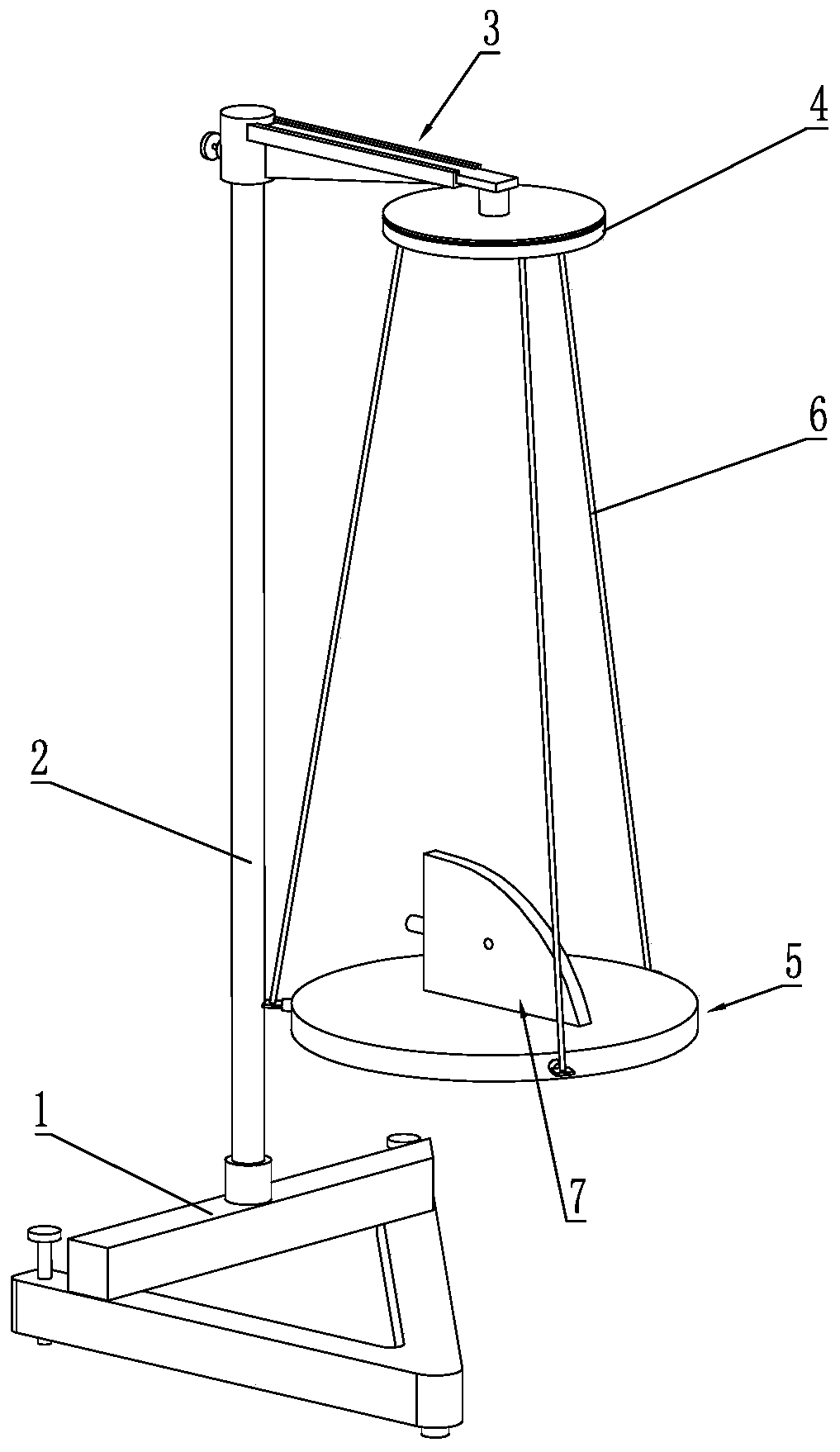
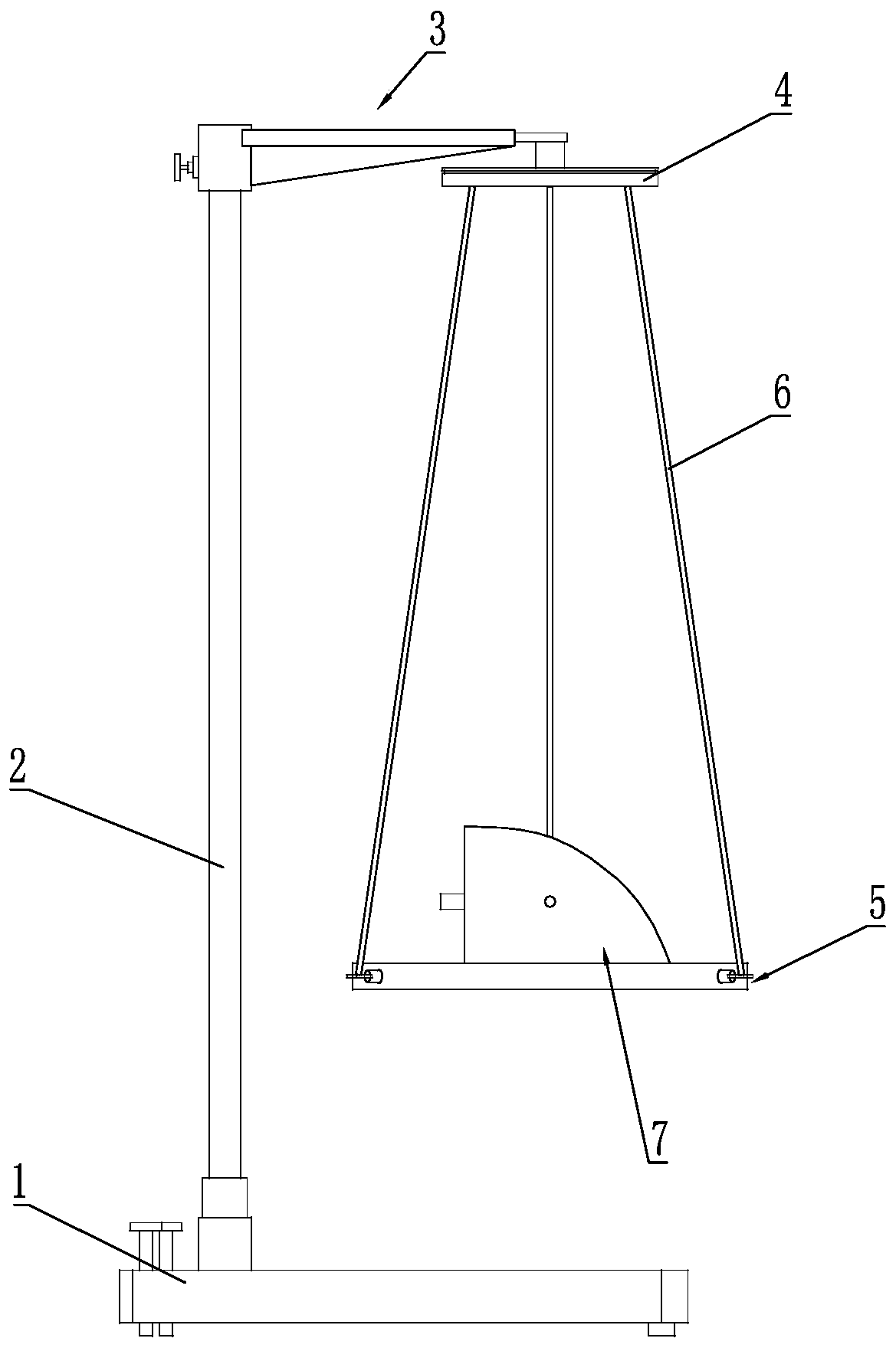
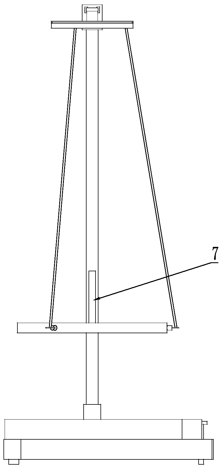
[0030] Such as Figure 1 to Figure 4 As shown, the rigid body accurately positioned three-line pendulum for verifying the vertical axis theorem of rigid body moment of inertia includes a base 1, a vertical rod 2 fixed on the base 1, a horizontal rod 3 fixed on the upper end of the vertical rod 2, an upper plate 4, The lower plate 5 and the three suspension wires 6 arranged between the upper plate 4 and the lower plate 5, the base 1 has a supporting function, and as the installation base of this embodiment, the upper plate 4 and the lower plate The plates 5 are arranged in parallel, and the upper plate 4 can rotate relative to the cross bar 3 to drive the lower plate 5 to rotate, wherein three suspension wires 6 are evenly arranged to connect the upper plate 4 with the lower plate 4. The disk 5 is connected, when the upper disk 4 rotates, the suspension wire 6 drives the lower disk 5 to rotate, so as to realize the rotation of the rigid body to be tested, and is used to realize...
Embodiment 2
[0046] Embodiment 2 is to further improve the lower wall 5 and the cross bar 3 on the basis of the first embodiment. Therefore, the same parts as the first embodiment will not be repeated here, and only the lower wall 5 It will be described in detail with the crossbar 3 .
[0047] see Figure 7 and Figure 8 , three mounting holes 52 are evenly distributed on the outer peripheral surface of the lower wall 5, and the centerlines of the three mounting holes 52 all intersect with a point on the axis line of the lower wall 5, and the three mounting holes Telescopic rods 53 are correspondingly installed in the holes 52, and the lower ends of the suspension wires 6 are fixedly connected to the outer ends of the telescopic rods 53. Since the telescopic rods 53 can slide in the mounting holes 52, when in use , the protruding position of the telescopic rod 53 relative to the outer peripheral surface of the lower plate 5 can be manually adjusted. Figure 7 , like this, the space that...
PUM
 Abstract
Description
Claims
Application Information
 - R&D
- Intellectual Property
- Life Sciences
- Materials
- Tech Scout
- Unparalleled Data Quality
- Higher Quality Content
- 60% Fewer Hallucinations
Browse by: Latest US Patents, China's latest patents, Technical Efficacy Thesaurus, Application Domain, Technology Topic, Popular Technical Reports.
© 2025 PatSnap. All rights reserved.Legal|Privacy policy|Modern Slavery Act Transparency Statement|Sitemap|About US| Contact US: help@patsnap.com


