Eureka AIR delivers breakthrough ideas for toughest innovation challenges, trusted by R&D personnel around the world.

A method for measuring the azimuth angle of a target with a vehicle-mounted radar and the vehicle-mounted radar

A technology of target orientation and vehicle radar, which is applied in the field of vehicle radar, can solve the problems of not meeting the real-time requirements of vehicle radar, high data rate requirements, and exceeding computing capacity, etc. Effect of value range

Active Publication Date: 2021-07-27
BEIJING JINGWEI HIRAIN TECH CO INC
View PDF7 Cites 0 Cited by
  • Summary
  • Abstract
  • Description
  • Claims
  • Application Information

AI Technical Summary

Problems solved by technology

Traditional super-resolution algorithms such as MUSIC, CAPON, and ESPRIT usually require multiple snapshots of radar data to perform angle measurement calculations, while vehicle-mounted radars have high data rate requirements and require the use of single snapshot data to complete angle measurement calculations. Not applicable
Although single-shot super-resolution algorithms such as the APES algorithm can use a single snapshot of the radar data to estimate the spatial spectrum, due to the large amount of calculation, it usually exceeds the computing power of the radar chip and cannot meet the real-time requirements of the vehicle radar.

Method used


Image

  • A method for measuring the azimuth angle of a target with a vehicle-mounted radar and the vehicle-mounted radar
  • A method for measuring the azimuth angle of a target with a vehicle-mounted radar and the vehicle-mounted radar
  • A method for measuring the azimuth angle of a target with a vehicle-mounted radar and the vehicle-mounted radar

Examples


Embodiment Construction

[0072] The following will clearly and completely describe the technical solutions in the embodiments of the present invention with reference to the accompanying drawings in the embodiments of the present invention. Obviously, the described embodiments are only some, not all, embodiments of the present invention. Based on the embodiments of the present invention, all other embodiments obtained by persons of ordinary skill in the art without making creative efforts belong to the protection scope of the present invention.

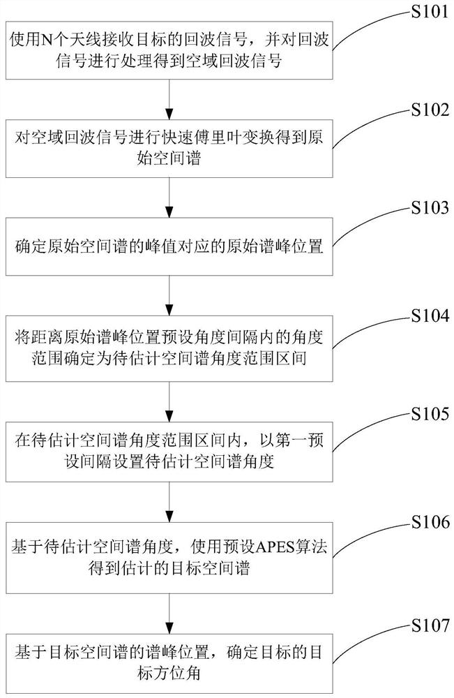
[0073] The embodiment of the present invention discloses a method for measuring the azimuth angle of a target with a vehicle-mounted radar and the vehicle-mounted radar. N antennas are used to receive the echo signals of the target, and the echo signals are processed to obtain the echo signals in the airspace. Fast Fourier is performed on the echo signals in the airspace. The original spatial spectrum is obtained by leaf transformation, the original spectral pe...


PUM


Abstract

The invention discloses a method for measuring the azimuth angle of a target by a vehicle-mounted radar and the vehicle-mounted radar. The space echo signal is obtained according to the echo signal of the received target, and the original spectrum peak corresponding to the peak value of the original spatial spectrum obtained according to the space echo signal is determined. Position, based on the original spectral peak position to determine the range of the spatial spectrum angle to be estimated, and set the spatial spectrum angle to be estimated, use the preset APES algorithm for the angle to obtain the estimated result of the target spatial spectrum, based on the estimated spectral peak position of the target spatial spectrum Estimate the target azimuth of the target. The present invention uses fast Fourier transform to obtain the interval of the range of the spatial spectrum angle to be estimated, which can reduce the value range of the original spatial spectrum angle to be estimated, and at the same time, the Q matrix in the preset APES algorithm is obtained only according to the sample correlation matrix, so that the Q matrix will be It does not change with the angle of the estimated space spectrum, and only needs to invert the Q matrix once, so the calculation of super-resolution angle measurement can be realized in a short time.

Description

technical field [0001] The invention relates to the technical field of vehicle radar, and more specifically, relates to a method for measuring the azimuth angle of a target by vehicle radar and the vehicle radar. Background technique [0002] Vehicle radar has become an irreplaceable sensor choice in intelligent driving solutions because of its good speed measurement ability for targets and good penetration ability for rain and fog. In order to achieve accurate two-dimensional positioning of the target, the vehicle-mounted radar needs to measure at least the distance between the target and the radar (that is, the slant distance) and the angle between the line between the target and the center of the radar relative to the direction of the center of the radar beam (that is, the azimuth of the target). [0003] At present, the commonly used target azimuth measurement scheme is: the vehicle radar uses N (N>1) antennas to receive the echo signals of the target; the echo signal...

Claims


Application Information

Patent Timeline
Patent Type & Authority Patents(China)
IPC IPC(8): G01S7/40
CPCG01S7/40G01S7/403
Inventor 刘长江李红润毛聪顾翔
Owner BEIJING JINGWEI HIRAIN TECH CO INC
Why Eureka
Eureka Blog
Learn More