Ubiquitous power Internet of Things monitoring method

A technology of power Internet of things and prediction models, which is applied in measurement devices, electrical components, circuit devices, etc., can solve problems that are difficult to meet the requirements of accuracy and adaptability, the connection between virtual and physical spaces is not close enough, and the complexity of power grid systems increases. Degradation function failure and other problems

Active Publication Date: 2019-11-26
JIANGSU FRONTIER ELECTRIC TECH +2
View PDF3 Cites 13 Cited by
  • Summary
  • Abstract
  • Description
  • Claims
  • Application Information

AI Technical Summary

Problems solved by technology

[0002] With the continuous improvement of the integration and intelligence of the ubiquitous electric power Internet of things complex system equipment, its design, development, testing, operation, maintenance and other life cycle costs have increased significantly. At the same time, the complexity of the power grid system has also greatly increased. The probability of its failure, performance degradation, and functional failure to occur
The current ubiquitous power Internet of Things equipment monitoring method has the following problems: the connection between virtual and physical space is not close enough. At present, in the process of ubiquitous power Internet of Things equipment monitoring, the connection between virtual space and physical space is limited to a single device such as a generator set. In the ubiquitous power Internet of Things of the power Internet of Things, the "generation-transmission-transformation-use" areas are not involved as a whole
The detection of complex power Internet of Things equipment at this stage is mainly driven by the monitoring data of power grid equipment in known ideal operating conditions, so it is difficult to meet the accuracy of real-time state evaluation and prediction of complex power grid system equipment in a dynamic and changeable operating environment and adaptive needs

Method used


Image

  • Ubiquitous power Internet of Things monitoring method
  • Ubiquitous power Internet of Things monitoring method
  • Ubiquitous power Internet of Things monitoring method

Examples


Embodiment Construction

[0026] In order to better understand the essence of the present invention, the present invention will be further described below in conjunction with specific embodiments and accompanying drawings.

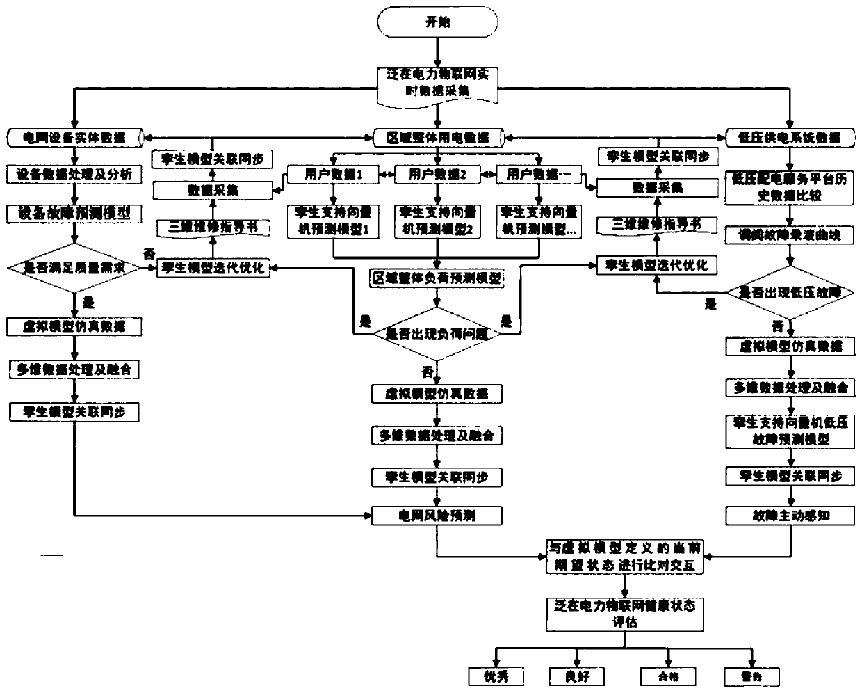
[0027] The invention discloses a monitoring method for the ubiquitous power Internet of things, the specific steps are as follows figure 1 Shown:

[0028] Step 1: Use data acquisition equipment to collect real-time data from each unit in the ubiquitous power Internet of Things. The collected real-time data is stored and managed for the life cycle data of ubiquitous power Internet of Things through distributed cloud server storage technology. data acquisition equipment such as Figure 4 As shown, it includes physical feature measurement and control equipment, protection measurement and control equipment, temperature monitoring equipment and operating environment monitoring equipment, etc. The collected data types include electrical parameters and non-electric parameters.

[0029...


PUM


Abstract

The invention discloses a ubiquitous power Internet of Things monitoring method, and belongs to the field of power grid control. The method comprises the following steps: acquiring real-time data of each unit in ubiquitous power Internet of Things by using data acquisition equipment; creating a corresponding digital twinning model according to the real-time data; and comparing and interacting thedigital twin model with a normal state, and monitoring the ubiquitous power Internet of Things in real time. According to the invention, real-time dynamic monitoring can be carried out on the power Internet of Things of each area.

Description

technical field [0001] The invention relates to a monitoring method for the ubiquitous power Internet of Things, which belongs to the field of power grid control. Background technique [0002] With the continuous improvement of the integration and intelligence of the ubiquitous electric power Internet of things complex system equipment, its design, development, testing, operation, maintenance and other life cycle costs have increased significantly. At the same time, the complexity of the power grid system has also greatly increased. The probability of its failure, performance degradation, and functional failure. The current ubiquitous power Internet of Things equipment monitoring method has the following problems: the connection between virtual and physical space is not close enough. At present, in the process of ubiquitous power Internet of Things equipment monitoring, the connection between virtual space and physical space is limited to a single device such as a generator ...

Claims


Application Information

Patent Timeline
Patent Type & Authority Applications(China)
IPC IPC(8): G06Q10/06G06Q50/06G06F17/50G06K9/62H02J3/00G01D21/02
CPCG06Q10/06375G06Q50/06H02J3/00G01D21/02G06F18/23213
Inventor 王松云尹飞祝永晋马吉科葛崇慧昆明李剑武梦阳厉文婕陈灰季聪
Owner JIANGSU FRONTIER ELECTRIC TECH
Why Eureka
Try Eureka