Turbine rotor assembling vehicle for engine and turbine rotor assembling method

A turbine rotor and engine technology, applied in the field of aero-engines, can solve problems such as hidden safety hazards, low assembly accuracy, high labor intensity, etc., and achieve the effect of saving site space, high assembly accuracy, and solving safe production.

Active Publication Date: 2019-11-29
CHINA HANGFA SOUTH IND CO LTD
View PDF6 Cites 3 Cited by
  • Summary
  • Abstract
  • Description
  • Claims
  • Application Information

AI Technical Summary

Problems solved by technology

[0003] The invention provides an engine turbine rotor assembly vehicle and a turbine rotor assembly method to solve the technical problems of the manual assembly method in the prior art, which has high labor intensity, low assembly precision, and large potential safety hazards.

Method used


Image

  • Turbine rotor assembling vehicle for engine and turbine rotor assembling method
  • Turbine rotor assembling vehicle for engine and turbine rotor assembling method
  • Turbine rotor assembling vehicle for engine and turbine rotor assembling method

Examples


Embodiment Construction

[0026] It should be noted that the embodiments in the application and the features in the embodiments can be combined with each other if there is no conflict. Hereinafter, the present invention will be described in detail with reference to the drawings and in conjunction with the embodiments.

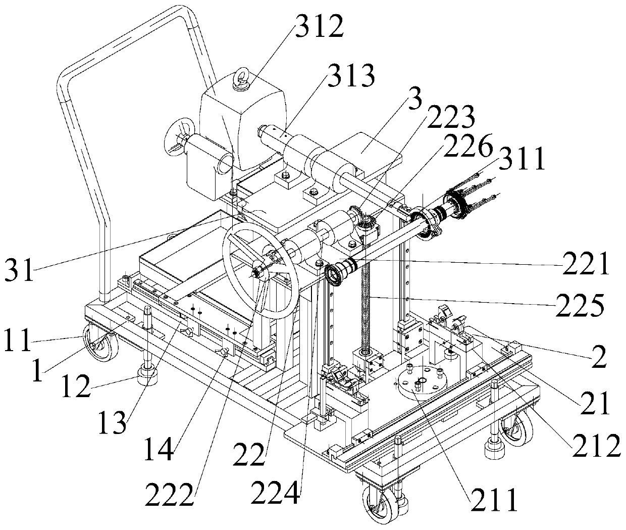
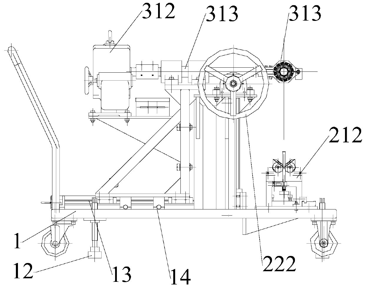
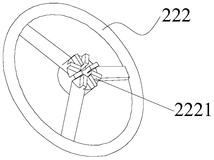
[0027] figure 1 Is a three-dimensional schematic diagram of an engine turbine rotor assembly vehicle according to a preferred embodiment of the present invention; figure 2 It is a front view of the engine turbine rotor assembly vehicle of the preferred embodiment of the present invention; image 3 Is a schematic diagram of the handwheel of the preferred embodiment of the present invention; Figure 4 It is a schematic diagram of the handwheel limit sitting of the preferred embodiment of the present invention.

[0028] Such as figure 1 with figure 2 As shown, the engine turbine rotor assembly vehicle of this embodiment includes: a frame body 1, which includes wheels 11 arranged in rolling an...


PUM


Abstract

The invention discloses a turbine rotor assembling vehicle for an engine and a turbine rotor assembling method. The turbine rotor assembling vehicle comprises a frame body. The frame body comprises wheels and a supporting part. A first assembling device for assembling a turbine rotor vertically and debugging axial runout of the turbine rotor is arranged on the frame body, and a second assembling device for clamping the turbine rotor to convert horizontal mounting and vertical assembling of the turbine robot is slidably arranged on the frame body; the second assembling device is arranged, wherein the horizontal distance is adjustable relative to the first assembling device to form an assembling space needed for vertically assembling the turbine rotor. The first assembling device is arranged, wherein the vertical height is adjustable relative to the second assembling device to from a conversion space where horizontal mounting and vertical assembling of the turbine rotor are converted. According to the turbine rotor assembling vehicle for the engine, all assembling links of the turbine robot can be finished on the turbine rotor assembling vehicle for the engine, so that the operatingprocess is simple and the assembling precision is high.

Description

Technical field [0001] The invention relates to the field of aeroengines, in particular, to an engine turbine rotor assembly vehicle. In addition, the present invention also relates to a turbine rotor assembly method using the above-mentioned engine turbine rotor assembly vehicle. Background technique [0002] At present, the assembly process of a certain type of aero engine turbine rotor is entirely manual assembly by workers, and tooling is used for testing and debugging after assembly. The turbine rotor is a key component of the engine. Its assembly process is relatively strict and the accuracy requirements are high. In addition, the turbine rotor itself has a certain weight. Therefore, workers manually carry the turbine rotor to each station every day. The potential safety hazard, and the probability of damage to the turbine rotor is high. In addition, the turbine rotor is a precision part with high manufacturing cost, and the cost amount is up to one million. Therefore, t...

Claims


Application Information

Patent Timeline
Patent Type & Authority Applications(China)
IPC IPC(8): B23P21/00
CPCB23P21/004
Inventor 许育辉彭彤瞿品祥陈毅能杨建军
Owner CHINA HANGFA SOUTH IND CO LTD
Why Eureka
Try Eureka