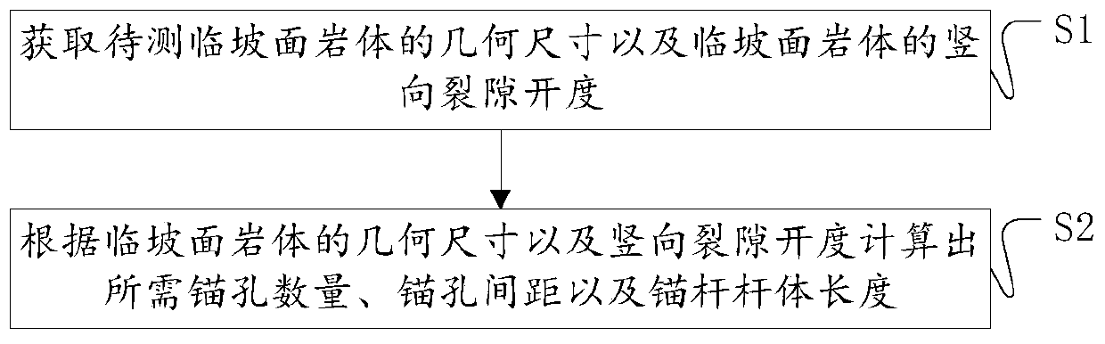
Near-slope-surface slope surface rock mass anchoring arrangement method
A technology for rock mass and slope surface, which is applied in the field of rock mass anchorage setting on the slope face, and can solve the problems of incapability of white arsenic sandstone support, loss of anchoring effect, and collapse of white arsenic sandstone.
- Summary
- Abstract
- Description
- Claims
- Application Information
AI Technical Summary
Problems solved by technology
Method used
Image

Examples
specific Embodiment 1
[0092] The rock mass 11 takes the white puffy sand rock mass 11 as an example. The anchor rod 14 is a hollow rod body, and high polymer is injected into the rod body. The high polymer is a two-component low-viscosity expanded polyurethane high polymer grouting material, which forms an anchor rod rod 14.
[0093] It is necessary to implement polymer anchor grouting on a certain white arsenic sandstone layer to improve its anti-overturning ability and avoid collapse, so as to prevent block-like gravity erosion. The anchor grouting design is implemented according to the following steps:
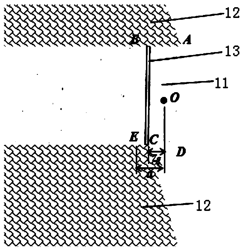
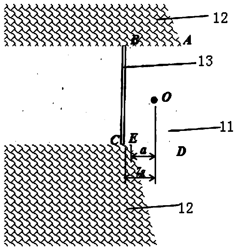
[0094] A. Determine the geometric dimensions of the white puffy sandstone body 11 on the slope face through on-site investigation, mainly including the height of the puffy sandstone body 11 on the slope face, the geometric size of the cross section and the opening degree of the vertical crack 13; please refer to figure 2 as well as image 3 , the target white sandstone body 11 to be tested is ...
specific Embodiment 2
[0150] It is necessary to implement high polymer anchor grouting on a certain white arsenic sandstone layer to prevent massive gravity erosion. The anchor grouting design is implemented according to the following steps:
[0151] A Determine the geometric dimensions of the Pisha sandstone body 11 on the slope surface through on-site investigation:
[0152] Please see figure 2 as well as image 3 , the target white arsenic sandstone body 11 to be tested is ABCD, the height is 2.0m, and the opening degree of the vertical crack 13 is 0.006m;
[0153] B determines the number of anchor rods 14 and the anchor hole spacing through stability analysis, mainly including:
[0154] B1 Determine the abscissa of the center of gravity of the section at the center of the width according to the geometric dimensions of the section, and the weight of the white sandstone body 11 per unit length along the horizontal direction is G=22.5kN / m;
[0155] B2 figure 2 As shown, the point at the inne...
PUM
| Property | Measurement | Unit |
|---|---|---|
| Height | aaaaa | aaaaa |
| Opening | aaaaa | aaaaa |
Abstract
Description
Claims
Application Information
 - R&D
- Intellectual Property
- Life Sciences
- Materials
- Tech Scout
- Unparalleled Data Quality
- Higher Quality Content
- 60% Fewer Hallucinations
Browse by: Latest US Patents, China's latest patents, Technical Efficacy Thesaurus, Application Domain, Technology Topic, Popular Technical Reports.
© 2025 PatSnap. All rights reserved.Legal|Privacy policy|Modern Slavery Act Transparency Statement|Sitemap|About US| Contact US: help@patsnap.com