Cable monitoring system

A monitoring system and cable technology, applied in the field of cable fault detection, can solve problems such as lack of monitoring, and achieve the effect of reducing the scope of troubleshooting and improving the efficiency of troubleshooting

Pending Publication Date: 2019-11-29
GUANGZHOU METRO GRP CO LTD
View PDF0 Cites 2 Cited by
  • Summary
  • Abstract
  • Description
  • Claims
  • Application Information

AI Technical Summary

Problems solved by technology

This kind of monitoring method can only judge the power failure or disconnection of a whole cable line or a certain loop. For cables with many transfer points and long lines, it is only a general direction; as follows figure 1 As shown, when any part of the monitoring cable is disconnected, there will be no current passing through the entire cable, so no current can be detected at the three current monitoring points A, B, and C, and only one cable can be judged to be power-off or open-circuit

Method used


Image

  • Cable monitoring system
  • Cable monitoring system
  • Cable monitoring system

Examples


Embodiment Construction

[0036] The preferred embodiments of the present invention will be described below in conjunction with the accompanying drawings. It should be understood that the preferred embodiments described here are only used to illustrate and explain the present invention, and are not intended to limit the present invention.

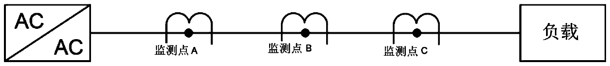
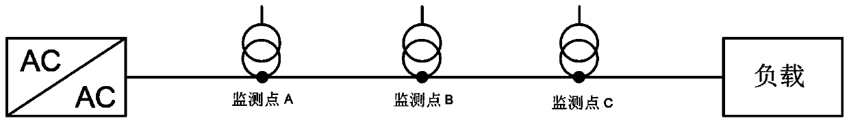
[0037] Such as Figure 1-7 As shown, the present invention provides a cable monitoring system, comprising:

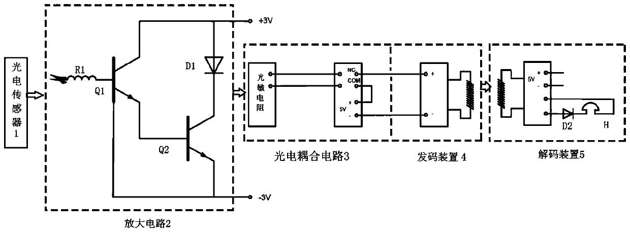
[0038] A number of voltage sensors 1 respectively arranged on each monitoring point of the cable, a detection device connected one-to-one with the voltage sensor 1, a coding device 4 connected one-to-one with the detection device, and a decoding device 5;

[0039] The voltage sensor 1 is used to collect the voltage signal on the monitoring point;

[0040] The detection device is used to drive the code sending device 4 to generate a code and send it to the decoding device 5 when the voltage signal is abnormal, wherein the code is used to indicate the position...


PUM


Abstract

The invention relates to the technical field of cable fault detection, and particularly discloses a cable monitoring system. The cable monitoring system comprises a plurality of voltage sensors, detection devices, code sending devices and a decoding device, wherein the plurality of voltage sensors are respectively arranged at each monitoring point of a cable; the detection devices are connected with the voltage sensors one to one; the code sending devices are connected with the detection devices one to one; the voltage sensors are used for acquiring voltage signals on the monitoring points; the detection devices are used for driving the code sending devices to generate codes and sending the codes to the decoding device when the voltage signals are abnormal, wherein the codes are used for indicating positions of the monitoring points; and the decoding device receives the codes and decodes so as to acquire and output position information of the monitoring points. According to the invention, a plurality of monitoring points are reasonably arranged on a cable line, and by detecting voltages on the monitoring points, a cable fault removal range is shortened, and troubleshooting efficiency is improved.

Description

technical field [0001] The invention relates to the technical field of cable fault detection, in particular to a cable monitoring system. Background technique [0002] In daily life, the cable line from the power box to the power input terminal of the load equipment generally needs to pass through the uninterruptible power supply system, the power panel distribution system, and many transfer terminals, and then connect to the input terminal of the power module of the load equipment after being connected section by section. When the power output is normal but the load equipment fails, the reason may be that any part of the cable line from the output end of the power supply to the input end of the power module of the load equipment is disconnected or poorly connected. Professional and technical personnel need to analyze and judge the cause of the fault, compress the fault range, and find the fault point. When the cable line is long, there are many transfer terminals, the wirin...

Claims


Application Information

Patent Timeline
Patent Type & Authority Applications(China)
IPC IPC(8): G01R31/08
CPCG01R31/083
Inventor 陈微郑文彬邓航张小虎陈启新龚聪范伟铭黄业康
Owner GUANGZHOU METRO GRP CO LTD
Why Eureka
Try Eureka