
Optical radar-based driving assisting method

A technology of driving assistance and radar, applied in the field of driving assistance based on optical radar, can solve problems such as vehicle real-time position error, signal blocking or interference, error, etc., and achieve the effect of improving accuracy and reducing the amount of calculation and error

Active Publication Date: 2019-11-29
HUA CHUANG AUTOMOBILE INFORMATION TECHN CENT
View PDF17 Cites 1 Cited by
  • Summary
  • Abstract
  • Description
  • Claims
  • Application Information

AI Technical Summary

Problems solved by technology

However, global satellite positioning systems are prone to bias due to factors such as climate, air or electromagnetic waves
In addition, if there are many obstacles around the vehicle, such as high-rise buildings near the vehicle, the signal is also easily blocked or interfered, which will cause errors or even errors in the real-time position of the vehicle

Method used


Image

  • Optical radar-based driving assisting method
  • Optical radar-based driving assisting method
  • Optical radar-based driving assisting method

Examples


Embodiment Construction

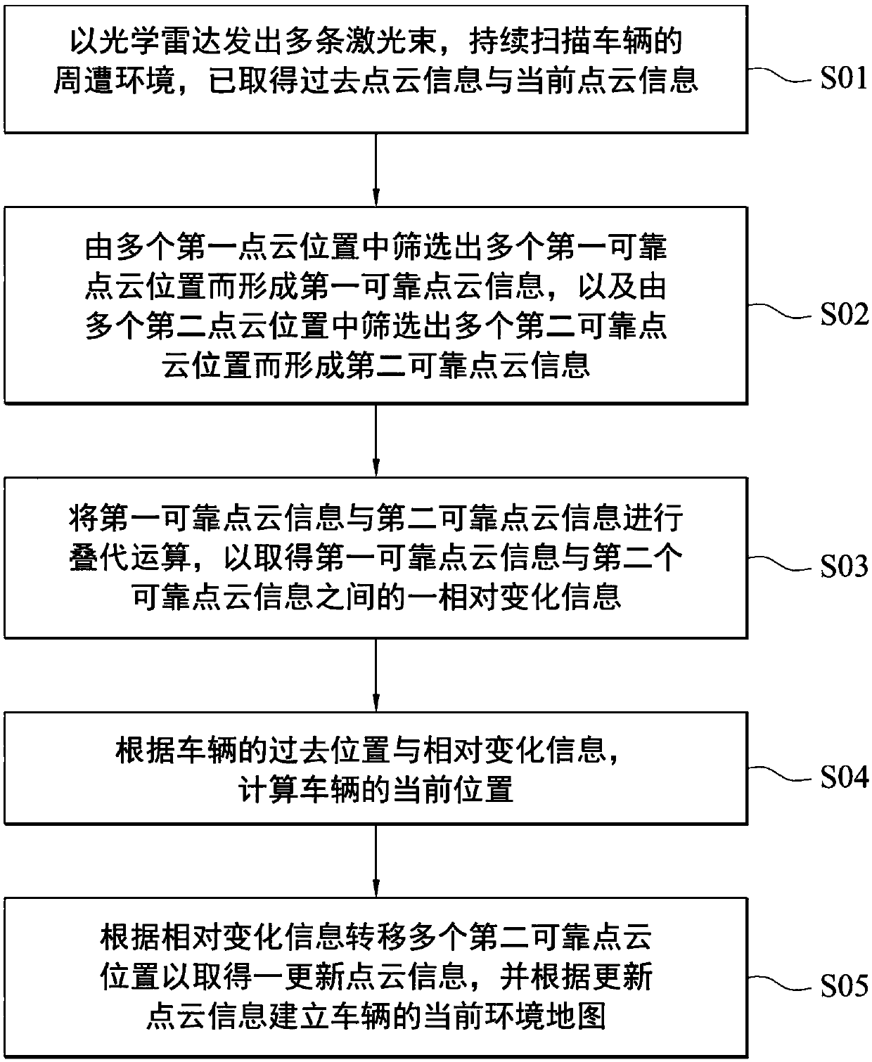
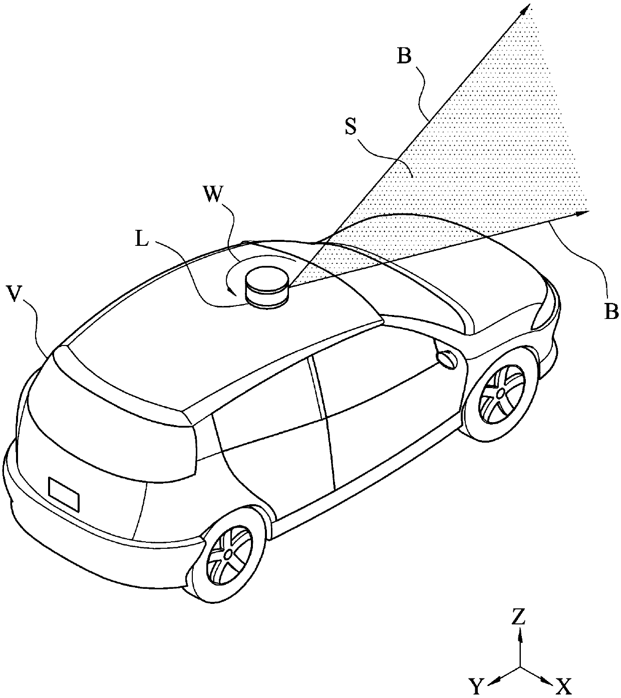
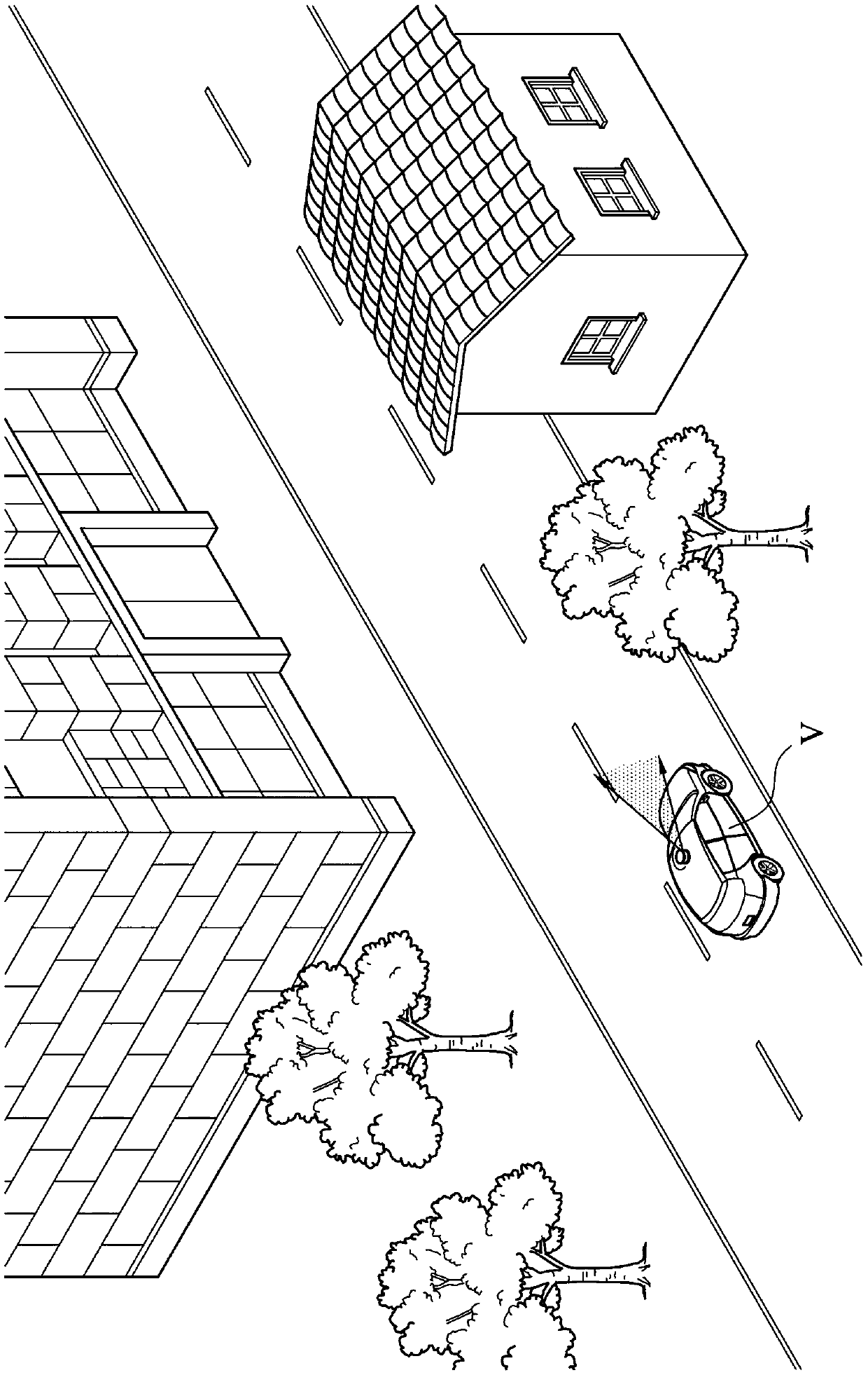
[0044] figure 1 It is a flowchart of the steps of an embodiment of the driving assistance method of the present invention. Such as figure 1 As shown, the driving assistance method of this embodiment is to continuously scan the surroundings of the vehicle V through the optical radar L to obtain point cloud (point cloud) information, and the point cloud information is processed and calculated to obtain an accurate environmental map and the location of the vehicle in the environment. The location in the map is used for various vehicle applications, such as navigation route planning, Internet of Vehicles, map data establishment or automatic driving, etc. Such as figure 1 As shown, the driving assistance method of this embodiment includes step S01 to step S05.

[0045] Firstly, step S01 can be performed: using a light detection and ranging (Lidar) to emit multiple laser beams B to continuously scan the surrounding environment of the vehicle V to obtain past point cloud informati...


PUM


Abstract

The invention discloses an optical radar-based driving assisting method. The method comprises the following steps that: an optical radar emits a plurality of laser beams to continuously scan the surrounding environment of a vehicle so as to acquire previous point cloud information and current point cloud information, wherein the previous point cloud information comprises a plurality of first pointcloud positions, and the current point cloud information comprises a plurality of second point cloud positions; a plurality of first reliable point cloud positions are screened from the first point cloud positions so as to form first reliable point cloud information, and a plurality of second reliable point cloud positions are screened from the second point cloud positions so as to form second reliable point cloud information; iterative operation is performed on the first reliable point cloud information and the second reliable point cloud information, so that the relative change informationbetween the first reliable point cloud information and the second reliable point cloud information is obtained; and the current position of the vehicle is calculated according to the previous positionof the vehicle and the relative change information.

Description

technical field [0001] The present invention relates to a driving assistance method, in particular to an optical radar-based driving assistance method. Background technique [0002] With the advancement of technology, many vehicles will be equipped with a positioning system to obtain the real-time location of the vehicle for various vehicle applications, such as navigation route planning, car networking or map information establishment, etc. [0003] At present, the real-time position of the vehicle is mainly achieved through the Global Positioning System (GPS). However, global satellite positioning systems are prone to bias due to factors such as climate, air or electromagnetic waves. In addition, if there are many obstacles around the vehicle, such as high-rise buildings near the vehicle, the signal is also easily blocked or interfered, which will cause errors or even errors in the real-time position of the vehicle. Contents of the invention [0004] In view of this, i...

Claims


Application Information

Patent Timeline
IPC IPC(8): G01S17/88
CPCG01S17/88
Inventor 林立宗陈元骏许志明许裕鸿林嘉育
Owner HUA CHUANG AUTOMOBILE INFORMATION TECHN CENT
Learn More