Composite insulator vibration deicing device and deicing method

A technology of composite insulators and power units, used in overhead installation, cable installation, electrical components, etc.

Active Publication Date: 2021-01-26
CHINA THREE GORGES UNIV
View PDF4 Cites 0 Cited by
  • Summary
  • Abstract
  • Description
  • Claims
  • Application Information

AI Technical Summary

Problems solved by technology

[0003] The main purpose of the present invention is to provide a vibration deicing device and deicing method for composite insulators, which can solve the problems of timely removing icing and avoiding high school operations for personnel

Method used


Image

  • Composite insulator vibration deicing device and deicing method
  • Composite insulator vibration deicing device and deicing method
  • Composite insulator vibration deicing device and deicing method

Examples


Embodiment 1

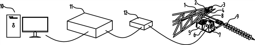
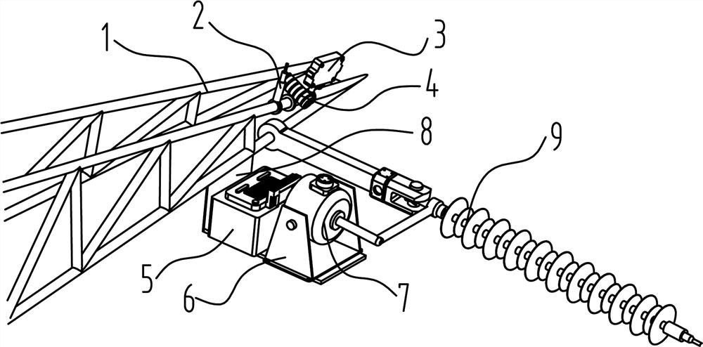
[0033]Such asFigure 1~10As shown, a composite insulator vibration deicing device and a deicing method include a power device fixedly connected to the elevated tower 1, and the power device is mechanically connected to the composite insulator 9; the power device is used to output and drive the composite insulator 9 along the axis Reciprocate in a straight line.

[0034]In a preferred solution, the platform 8 in the power plant is fixedly connected to the elevated tower 1, and the deicing device 7 is provided on the platform 8. With this structure, the device is fixedly connected to the elevated tower 1 to prevent the device from loosening or falling , Easy to use and reliable.

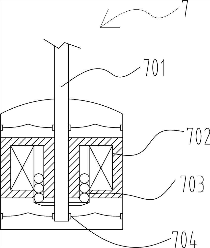
[0035]In a preferred solution, the ejector rod 701 in the deicing device 7 passes through the excitation coil 702 and is connected to the moving coil 703. One end of the ejector rod 701 is provided with a support spring 704, and the other end of the ejector rod 701 is provided with a chuck 705. The head 705 is fixe...

Embodiment 2

[0043]It is further explained in conjunction with Example 1, such asFigure 1~10As shown, when the camera 3 on the elevated tower 1 monitors the on-site ice thickness to meet the requirements; the control host 10 sends a command to the sweep signal generator 11; the sweep signal generator 11 receives the command and sends a specific frequency to the power amplifier 12 ; The frequency is amplified by the power amplifier 12 and then transmitted to the deicing device 7 over a long distance; the deicing device 7 is activated for vibration deicing.

Embodiment 3

[0045]In combination with the above embodiments, it will be further explained, such asFigure 1~10As shown, the test shows that the first 6 modes of the composite insulator 9 are all concentrated at low-order frequencies, and the first-order characteristic frequency is 29.37 Hz. The vibration characteristics of the composite insulator 9 are mainly based on the bending mode. At this time, the vibration has little effect on the bonding stability between the shed material and the core rod; the middle of the shed of the composite insulator 9, that is close to the core rod, has the largest stress. It can reach 0.8Mpa, and when extending from the shaft center to the surroundings, the stress generated gradually decreases. The stress at the edge of the umbrella skirt is about 0.4Mpa. As a result of the test, the deicing device 7 uses the SA-JZ005 type vibration exciter, which can operate normally in the low frequency range and can generate an exciting force of about 15000 N / m2, which can mee...


PUM


Abstract

The invention provides a composite insulator vibrating deicing device and deicing method, including a power device fixedly connected to the elevated tower, the power device is mechanically connected with the composite insulator; the power device is used to output and drive the composite insulator along the axial line Reciprocating motion; the device has good deicing effect, high efficiency, simple operation, safe and reliable use, strong versatility, quick response to monitoring and removing ice coating; using solar batteries, making full use of solar green energy, can be used for a long time, and has a long service life Long; avoid personnel working at heights, improve the safety of deicing operations; use deicing device vibration deicing, will not cause insulator flashover phenomenon, to ensure normal and efficient transportation of electricity.

Description

Technical field[0001]The invention relates to the technical field of deicing, in particular to a composite insulator vibration deicing device and a deicing method.Background technique[0002]In the current high-altitude composite insulator deicing industry, the safe operation of transmission lines is a key issue in the development of today’s power, especially in the natural environment. With the changes in the weather, transmission lines continue to suffer from wind and rain. Performance will be affected. Due to the frequent occurrence of snow and ice disasters in my country, icing poses a great threat to the construction of my country’s power grid, especially after the insulators are iced, the adjacent umbrella skirts are easily bridged by the icing, which greatly shortens the leakage distance of the insulators and is easy to cause icing. Flashover accidents and excessive icing of insulators will increase the load-bearing burden of umbrella skirts, fittings and transmission wires, ca...

Claims


Application Information

Patent Timeline
Patent Type & Authority Patents(China)
IPC IPC(8): H02G7/16
CPCH02G7/16
Inventor 秦红玲朱合法蒋明赵汉棣苏丹
Owner CHINA THREE GORGES UNIV
Why Eureka
Try Eureka