
Quantum information transmission method and system

A quantum information and transmission method technology, applied in the field of automation control, can solve the problems of increased information decoding delay, no simultaneous output, and complex protocol implementation, achieving the effects of simple implementation, improved synchronization flexibility, and good scalability.

Inactive Publication Date: 2019-11-29
UNIV OF SCI & TECH OF CHINA
View PDF6 Cites 0 Cited by
  • Summary
  • Abstract
  • Description
  • Claims
  • Application Information

AI Technical Summary

Problems solved by technology

For example, information is transmitted through codec protocols with built-in clock recovery such as 8b10b. This method is mature and standardized, but the implementation of the protocol is complicated. Functions such as clock recovery are not required in the homologous clock system. The complex protocol implementation also makes the decoding of information difficult. The delay becomes larger
Another example: add an accompanying clock, use multiple signal lines to transmit information in parallel, and send the clock signal at the same time when the sending end sends data. This method is also relatively simple, but the disadvantage is that the number of cables has changed a lot, and the current Many devices in China do not have the function of simultaneous output

Method used


Image

  • Quantum information transmission method and system
  • Quantum information transmission method and system
  • Quantum information transmission method and system

Examples


Embodiment Construction

[0021] In order to make the objectives, technical solutions, and advantages of the present invention clearer, the following further describes the present invention in detail in conjunction with specific embodiments and with reference to the accompanying drawings.

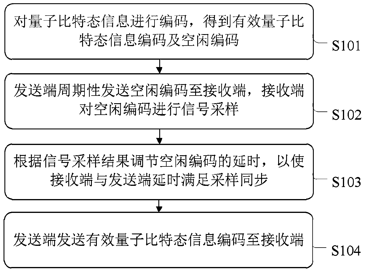
[0022] See figure 1 , figure 1 It is a flowchart of a quantum information transmission method proposed in an embodiment of the present invention. The method can be used for classical information transmission of low-latency qubit measurement, such as figure 1 As shown, the method includes:

[0023] S101: Encode qubit state information to obtain effective qubit state information encoding and idle encoding.

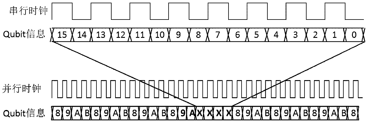
[0024] In this embodiment, using the finite state characteristics of the qubit, the four state information of the qubit |0>, |1>, |2>, NULL are respectively coded as 00, 01, 10, 11, where the code 00 , 01, 11 are valid qubit state information codes, and code 10 is idle codes, as shown in Table 1.

[0025] Quantum sta...


PUM


Abstract

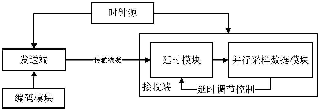
The invention discloses a classical information transmission method and system for low-delay quantum bit measurement, and the method comprises the steps: carrying out the coding of quantum bit state information, and obtaining an effective quantum bit state information code and an idle code; enabling the sending end to periodically send an idle code to the receiving end, and enabling the receivingend to perform signal sampling on the idle code; adjusting the delay of the idle code according to the signal sampling result, so that the delay of the receiving end and the sending end meets the sampling synchronization; and enabling the sending end to send the effective quantum bit state information code to a receiving end. The method is simple in coding rule and low in information transmissiondelay, the system has good expansibility, implementation is easy, resource consumption is low, large-scale integration can be achieved conveniently and rapidly, and synchronization flexibility is greatly improved.

Description

Technical field [0001] The invention relates to the field of automation control, in particular to a quantum information transmission method and system. Background technique [0002] In the field of automation control, there are several commonly used methods for low-latency transmission of information between multiple homologous clock-controlled digital systems. For example, information is transferred through codec protocols with built-in clock recovery such as 8b10b. The method is mature and standardized, but the protocol is complex to implement, and functions such as clock recovery are not required in the homologous clock system. The complex protocol implementation also enables information decoding The delay becomes larger. Another example: increase the associated clock, use multiple signal lines to transmit information in parallel, and send the clock signal at the same time when the sender sends data. This method is relatively simple, but the disadvantage is that the number of...

Claims


Application Information

Patent Timeline
Patent Type & Authority Applications(China)
IPC IPC(8): H04L9/08
CPCH04L9/0858
Inventor 林金梁福田徐昱孙丽华郭成李娜陈福升廖胜凯彭承志朱晓波潘建伟
Owner UNIV OF SCI & TECH OF CHINA
Learn More