Ventilation and dehumidification equipment for grain storage

A technology of grain and equipment, applied in the field of ventilation and dehumidification equipment for grain storage, can solve the problems of inconvenient adjustment of air output and moisture absorption, and difficulty in ensuring the uniformity of the air, and achieve the effect of improving the uniformity of the air

Active Publication Date: 2020-07-24
界首市云飞粮机有限公司
View PDF4 Cites 0 Cited by
  • Summary
  • Abstract
  • Description
  • Claims
  • Application Information

AI Technical Summary

Problems solved by technology

[0006] (1) Through the arrangement of ventilators, dehumidifiers and connecting seats and spiral pipes, the operation of ventilating hot air and absorbing moisture in the grain storage area can be realized. The two do not interfere with each other and can be controlled independently, and the use of spiral pipes can greatly improve The uniformity of the air outlet when the equipment is ventilated by hot air ensures better ventilation and dehumidification in the grain storage area. The air volume and moisture absorption can be controlled and adjusted freely to better cope with different grain storage area environments, and to solve the difficulty in performing ventilation and dehumidification operations on grain storage areas in the prior art, and to adjust the air volume and moisture absorption during the ventilation and dehumidification process. The volume is inconvenient to adjust, and at the same time it is difficult to guarantee the uniformity of the air outlet.

Method used


Image

  • Ventilation and dehumidification equipment for grain storage
  • Ventilation and dehumidification equipment for grain storage
  • Ventilation and dehumidification equipment for grain storage

Examples


Embodiment Construction

[0030] The following will clearly and completely describe the technical solutions in the embodiments of the present invention with reference to the accompanying drawings in the embodiments of the present invention. Obviously, the described embodiments are only some, not all, embodiments of the present invention. Based on the embodiments of the present invention, all other embodiments obtained by persons of ordinary skill in the art without creative efforts fall within the protection scope of the present invention.

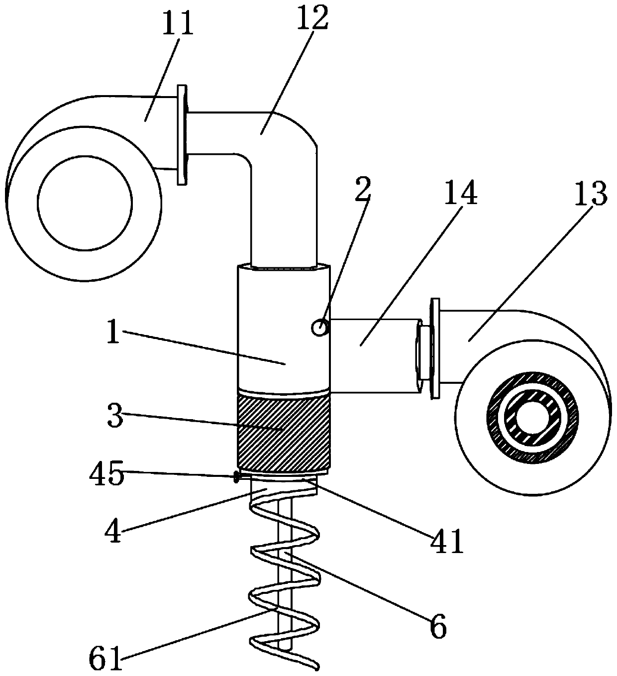
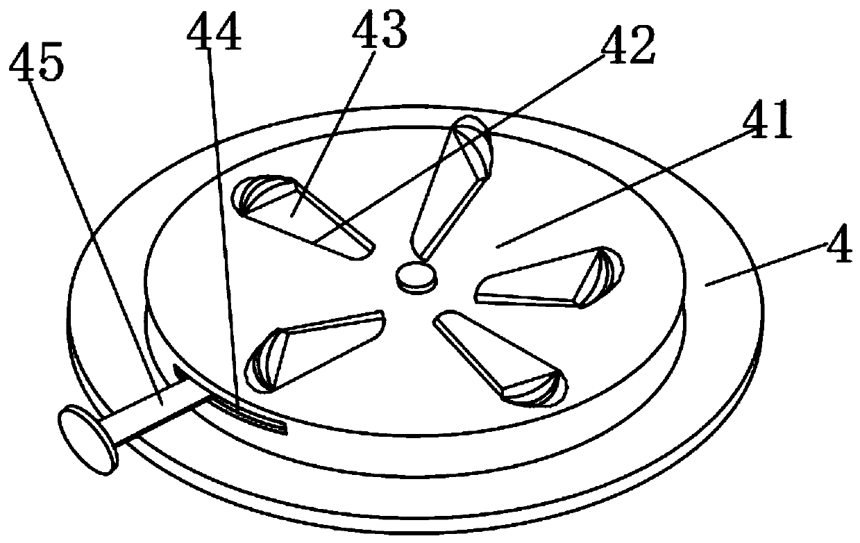
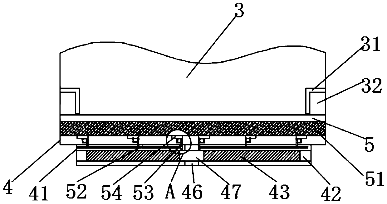
[0031] see Figure 1-5 As shown, the present embodiment provides a ventilation and dehumidification device for grain storage, including a connection base 1, a ventilator 11 and a dehumidifier 13, a first connecting pipe 12 is fixedly installed on the outer surface of the upper end of the connection base 1, and the connection base 1 A second connecting pipe 14 is fixedly installed on the outer surface of one side. The fan 11 is fixedly connected to the connecting se...


PUM


Abstract

The invention discloses a ventilation and dehumidification device for grain storage, which comprises a connecting seat, a ventilator and a dehumidifier. A first connecting pipe is fixedly installed on the outer surface of the upper end of the connecting seat, and a first connecting pipe is fixedly installed on one side of the outer surface of the connecting seat. There is a second connecting pipe, the ventilator is fixedly connected to the connecting seat through the first connecting pipe, and the dehumidifier is fixedly connected to the dehumidifier through the second connecting pipe. The operation can improve the uniformity of the air outlet when the equipment is ventilating hot air, and can also freely adjust the size of the vents during the ventilation and dehumidification process to better cope with different grain storage area environments. At the same time, the particles and dust adsorbed during the dehumidification process Impurities can be filtered to prevent dust from entering the dehumidifier and affecting the use. At the same time, the filter can be cleaned regularly to ensure the normal operation of the filter.

Description

technical field [0001] The invention relates to the field of ventilation and dehumidification equipment, in particular to a ventilation and dehumidification equipment for grain storage. Background technique [0002] Grain storage refers to the storage and management process of grain from harvest to consumption. During the storage period, grain is still a physiologically active organism and is under the influence of various environmental conditions. The environment includes physical and biological factors. These internal and external factors They are all closely related to the safe storage of grain. In the case of low water content and low ambient temperature, the respiratory intensity is weak, but it can maintain the minimum life activities, which is beneficial to storage. Therefore, it is necessary to create a good environment for the grain storage area. environment of; [0003] Existing ventilation and dehumidification equipment for grain storage are mostly installed sepa...

Claims


Application Information

Patent Timeline
Patent Type & Authority Patents(China)
IPC IPC(8): A01F25/22A23B9/08B01D46/10B01D46/00B01D53/26
CPCA01F25/22A23B9/08B01D46/10B01D53/261B01D2257/80B01D46/681
Inventor 李金玉
Owner 界首市云飞粮机有限公司
Why Eureka
Try Eureka