Rotary welding tool for friction welding and welding method

A friction welding and spin welding technology, used in welding equipment, manufacturing tools, non-electric welding equipment, etc., can solve the problems of easy wear, fracture, and single joint form of stirring tools, and achieve the effect of easy wear and tear.

Active Publication Date: 2019-12-03
NORTHWESTERN POLYTECHNICAL UNIV
View PDF10 Cites 5 Cited by
  • Summary
  • Abstract
  • Description
  • Claims
  • Application Information

AI Technical Summary

Problems solved by technology

[0007] In order to avoid the deficiencies of the prior art, the present invention proposes a rotary welding tool and a welding method for friction welding, which solves the problem of the single welding joint form of the existing rotary friction welding and linear friction welding, and the friction stir welding stirring tool is easy to wear and broken problems

Method used


Image

  • Rotary welding tool for friction welding and welding method
  • Rotary welding tool for friction welding and welding method
  • Rotary welding tool for friction welding and welding method

Examples


Embodiment 1

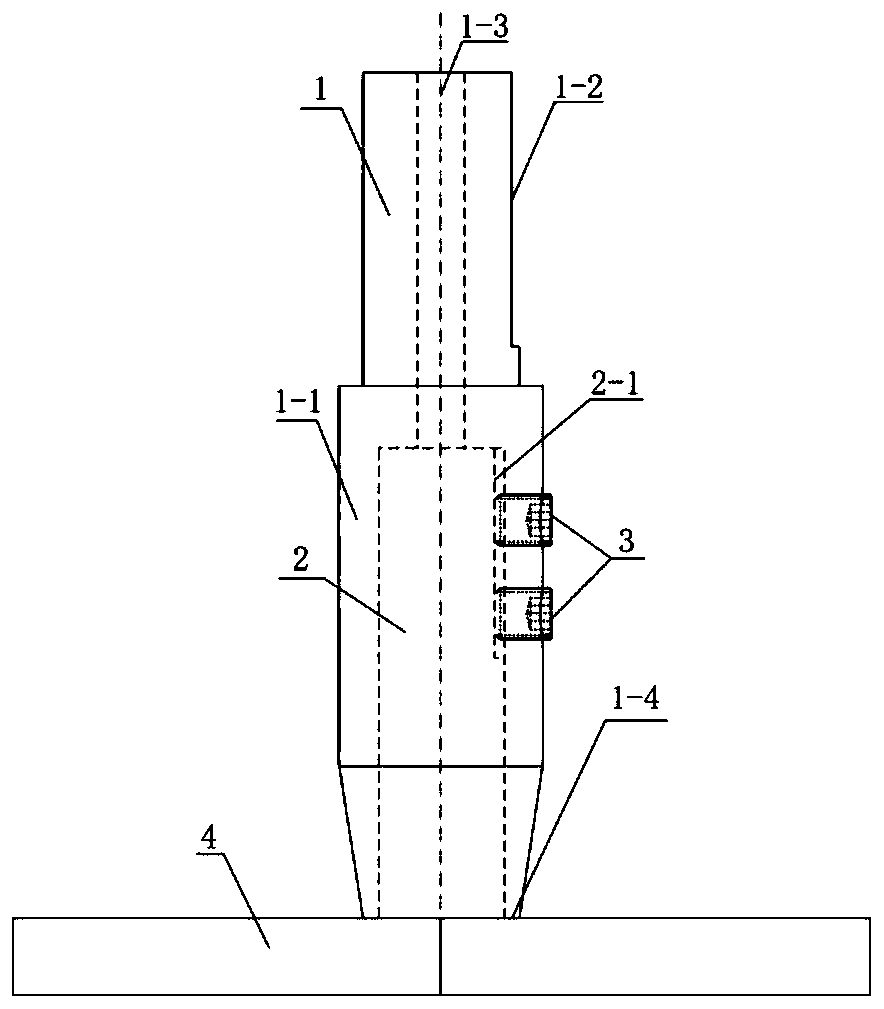
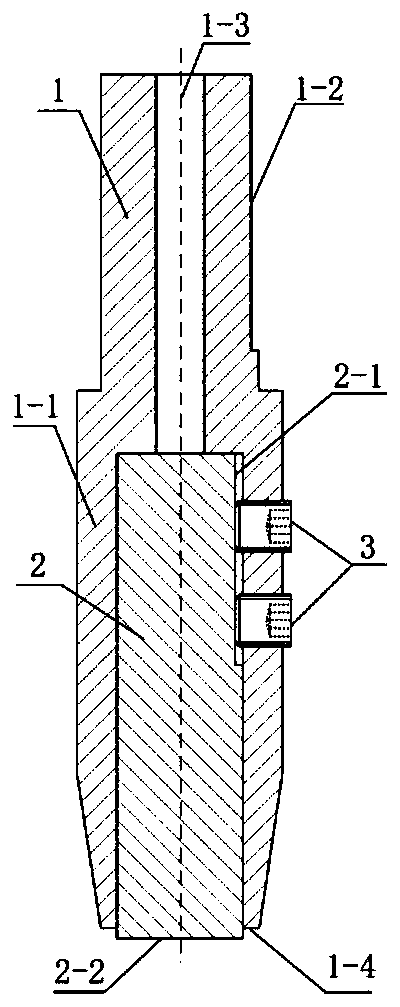
[0032] Implementation Example 1: Combining figure 1 with figure 2 This embodiment will be described. This embodiment includes a support body 1 , a core material 2 , a hexagon socket stud 3 and a workpiece 4 to be welded. Support body 1 is made up of sleeve 1-1, handle of a knife 1-2 and the through hole 1-3 that is built in the central axis of handle of a knife. The upper end of the core material 2 is provided with a clamping surface 2-1. Core material 2 is closely matched with sleeve 1-1, and is fixed by hexagon socket head bolt 3 and clamping surface 2-1. The through hole 1-3 inside the knife handle 1-2 can be used during disassembly. The core material end 2-2 protrudes 0-3 mm beyond the support body end 1-4. During welding, the supporting body 1 is connected with the main shaft of the welding machine through the handle 1-2. The main shaft of the welding machine transmits the torque to the core material 2 through the support body 1 . At a rotational speed of 10-2000 ...

Embodiment 2

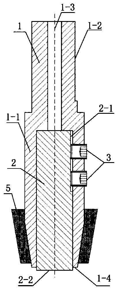
[0033] Implementation Example 2: Combining Graphs 1 and image 3 This embodiment will be described. The difference between this embodiment and Embodiment 1 is that the outside of the sleeve 1-1 is wrapped by circulating coolant 5 to reduce the temperature of the core material 2 and maintain the transmission of torque from the core material 2 to the workpiece 4. Other implementation steps are the same as implementation example 1.

Embodiment 3

[0034] Implementation Example 3: Combining Figure 4 This embodiment will be described. The difference between this embodiment and Embodiment 1 is that the joint form of the workpieces 4-1 and 4-2 is lap joint. Other implementation steps are the same as implementation example 1.


PUM

PropertyMeasurementUnit
thicknessaaaaaaaaaa

Abstract

The invention relates to a rotary welding tool for friction welding and a welding method, which achieve welding by friction of a rotary welding tool on the surface of a workpiece. The welding tool forrealizing the friction welding method consists of a core material and a support body. The core material is a consumable material and is composed of a cylinder or a prism made of the same material asa to-be-welded material. One end of the support body is sleeve-shaped and is in close fit with the core material; and the other end is a common knife handle connected with a motor spindle. The supportbody is a non-consumable part, and the material strength of the support body is higher than that of to-be-welded materials. Compared with common linear friction welding and rotary friction welding, butt joint, lap joint and spot welding of plates can be welded through mutual friction of homogeneous materials, and the friction welding method is not limited to workpieces with specific section shapes any more. Compared with common friction stir welding, a non-consumable stirring tool is not needed to serve as a welding tool any more, and the problem that a stirring head is prone to abrasion andbreakage is fundamentally solved.

Description

technical field [0001] The invention belongs to the field of welding technology, and relates to a rotary welding tool for friction welding and a welding method, in particular to a method for performing friction welding on the surface of a workpiece by using a welding tool of the same material as the workpiece. Background technique [0002] Existing friction welding techniques generally utilize mutual friction between workpieces (such as rotational friction welding and linear friction welding) or between workpieces and non-consumable tools inserted into the workpiece (such as friction stir welding) to generate heat , soften the material to be welded and form a plastic flow, thereby breaking the original interface to form an effective connection. [0003] For the existing friction welding technology, limited by the process characteristics, the joint forms welded by rotary friction welding and linear friction welding are relatively simple, and the two can only be used to weld w...

Claims


Application Information

Patent Timeline
Patent Type & Authority Applications(China)
IPC IPC(8): B23K20/12
CPCB23K20/1255
Inventor 刘小超甄云乾王啸李文亚陈海燕申志康曾尼鑫衡泽凤张雨彤
Owner NORTHWESTERN POLYTECHNICAL UNIV
Why Eureka
Try Eureka