

Mold core for molding glass
A glass and mold core technology, which is applied in glass forming, glass pressing, glass manufacturing equipment, etc., can solve the problems of reduced service life of diamond tools, improve machinability, surface roughness and cracks, etc. Effect of reducing chemical abrasiveness
- Summary
- Abstract
- Description
- Claims
- Application Information
AI Technical Summary
Problems solved by technology
Method used
Image

Examples
Embodiment 1
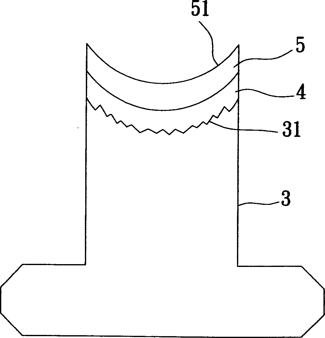
[0040] In a specific embodiment 1 of the mold core for glass molding of the present invention, the base material 3 is made of WC, the intermediate film 4 is a nitride containing titanium and has a thickness of 100 nm, and the protective film 5 is made of Pd - Crystallized precious metal layer of Ru-Ta-C with a thickness of 20 μm. In this specific example 1, the ratio of Pd wt%: Ru wt%: Ta wt%: C wt% is about 83:2:5:10.
[0041] The manufacturing method of the mold core for glass molding of this specific example 1 will be briefly described below.
[0042] First, a shaping surface with low surface precision and an aspheric shape is formed on a WC substrate, so as to form the substrate 3 having a similar shaping surface 31 .
[0043] Further, the interlayer film 4 containing titanium nitride is formed on the shaping surface 31 by sputtering in a vacuum system.
[0044] Next, using the same vacuum system, methane (CH) with a gas flow ratio of 1:4 was passed through. 4 ) and arg...
specific Embodiment 2
[0049] A specific embodiment 2 of the mold core for glass molding of the present invention is substantially the same as the specific embodiment 1, and the difference is that the protective film 5 is a crystallized noble metal layer containing Ir-Ru-C. In the second embodiment, the ratio of Irwt%:Ruwt%:Cwt% is about 33:22:45.
[0050] The manufacturing method of the mold core for glass molding in the second embodiment is basically the same as that in the first embodiment. The difference lies in that the crystallized noble metal layer containing Ir-Ru-C is sputtered, and CH with a gas flow ratio of 5:1 is passed through it. 4 and Ar and the working pressure is 10mTorr in the reaction chamber, a predetermined power is applied to an alloy target composed of Ir-Ru with a weight percentage of 62:38 to form an Ir- A Ru-C precious metal layer with a thickness of about 20 μm, and at the same time, a temperature rise treatment of 650° C. was performed on the test piece holder on which ...
specific Embodiment 3
[0052] The third embodiment of the mold core for glass molding of the present invention is substantially the same as the second embodiment, except that the protective film 5 is a crystallized noble metal layer containing Ir-Re-C. In this specific example three, the Ir wt%:Re wt%:C wt% is about 45:5:50.
[0053] The manufacturing method of the mold core for glass molding in the third embodiment is basically the same as that in the second embodiment. The difference is that the palladium material used is an alloy target composed of Ir-Re with a weight percentage of 89:11, and CH 4 And the gas flow ratio of Ar is 6:1.
[0054] It is worth mentioning that, since both Ir and Ru in the second embodiment have 3 unpaired electrons, and Re in the third embodiment has 5 unpaired electrons, C in the third embodiment has 5 unpaired electrons. The content needs to be higher than the C content of the second embodiment.
[0055] Through the above description, the protective films 5 of the ...
PUM
| Property | Measurement | Unit |
|---|---|---|
| thickness | aaaaa | aaaaa |
| thickness | aaaaa | aaaaa |
| thickness | aaaaa | aaaaa |
Abstract
Description
Claims
Application Information