Laser cutting machine cross beam of roller transmission system

A laser cutting machine and transmission system technology, applied in laser welding equipment, welding equipment, metal processing equipment, etc., can solve the problems of complicated installation process, relatively loud noise, difficult replacement, etc., and achieve high operating speed, long service life, The effect of simple process

Inactive Publication Date: 2019-12-03
江苏卡米特激光智能科技有限公司
View PDF0 Cites 3 Cited by
  • Summary
  • Abstract
  • Description
  • Claims
  • Application Information

AI Technical Summary

Problems solved by technology

[0003] In the laser cutting machine, the beam of the existing laser cutting machine is generally welded by steel plate, its weight is heavy, its rigidity is not good, and it is easy to deform. Most of them use gear racks and linear guide rails to move the laser cutting head to complete the cutting through the sliding plate. During the process, it is necessary to consider how to align the rack and the guide rail to ensure the parallelism between the guide rail and the rack. The installation process is complicated and relatively noisy. Because ball guide rails are generally used, if the slider is damaged, the track must be replaced. Difficult and difficult to maintain, therefore, a laser cutting machine beam with roller transmission system is proposed to solve the above problems

Method used


Image

  • Laser cutting machine cross beam of roller transmission system
  • Laser cutting machine cross beam of roller transmission system
  • Laser cutting machine cross beam of roller transmission system

Examples


Embodiment Construction

[0014] The following will clearly and completely describe the technical solutions in the embodiments of the present invention with reference to the accompanying drawings in the embodiments of the present invention. Obviously, the described embodiments are only some, not all, embodiments of the present invention. Based on the embodiments of the present invention, all other embodiments obtained by persons of ordinary skill in the art without making creative efforts belong to the protection scope of the present invention.

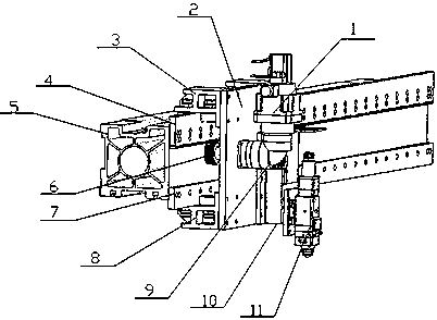
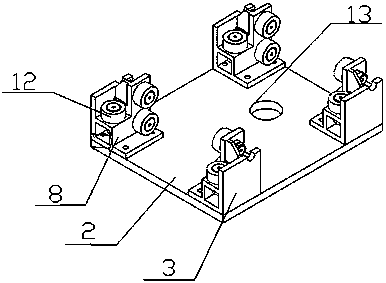
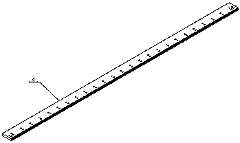
[0015] see Figure 1-3 As shown, a beam of a laser cutting machine with a roller transmission system includes an aluminum profile beam on which an integrated guide rail rack 4 and a guide rail 7 are installed, and the integrated guide rail rack 4 and guide rail 7 sides The upper roller group 3 and the lower roller group 8 are connected to each other; the upper roller group 3 and the lower roller group 8 are connected to the slide plate 2 by screws, and the sli...


PUM


Abstract

The invention discloses a laser cutting machine cross beam of a roller transmission system. The laser cutting machine cross beam comprises a motor, a slide carriage, an upper roller set, an integratedguide rail rack, an aluminum profile cross beam, a driving gear, a guide rail, a lower roller set, a speed reducer, a sliding table, a laser head, a bearing flat roller and a mounting hole. Accordingto the invention, a cast aluminum profile is used as a main body, so that the weight is lighter, the rigidity is good, and the process is simple; the roller sets and the guide rail rack are integrally matched and are connected with a laser head to complete the movement, with the arrangement of the integrated rack guide rail, the complex alignment work between the guide rail and the rack during mounting is saved, and the precision requirement of the mounting reference is reduced; a roller guide rail system is composed of the roller bearings and is lower in noise, when the roller guide rail isassembled, the concentric rollers and the adjusting rollers are used in cooperation, the pre-tightening between the rollers and the guide rails can be adjusted at any time by adjusting the eccentric distances of the rollers, and the worn guide rails or rollers can be independently replaced without replacing all the guide rails or rollers.

Description

technical field [0001] The invention relates to a beam of a laser cutting machine, in particular to a beam of a laser cutting machine with a roller transmission system, and belongs to the technical field of laser cutting applications. Background technique [0002] As a new type of thermal cutting technology, laser cutting has the advantages of fast cutting speed, high production efficiency and small heat-affected zone, and has become one of the main cutting methods for metal sheets. The speed requirements of cutting machines are also getting higher and higher, and the cutting precision requirements are also getting higher and higher. Laser cutting machines are developing in the direction of high speed and high response. [0003] In the laser cutting machine, the beam of the existing laser cutting machine is generally welded by steel plate, its weight is heavy, its rigidity is not good, and it is easy to deform. Most of them use gear racks and linear guide rails to move the ...

Claims


Application Information

Patent Timeline
Patent Type & Authority Applications(China)
IPC IPC(8): B23K26/38B23K26/08
CPCB23K26/0869B23K26/38
Inventor 陈章谢杰
Owner 江苏卡米特激光智能科技有限公司
Why Eureka
Try Eureka