A positioning device for assembling heat dissipation fins of an evaporator

A technology of positioning device and cooling fins, applied in auxiliary devices, metal processing equipment, auxiliary welding equipment, etc., can solve the problems of low efficiency and labor consumption, and achieve the effect of ensuring positioning effect, good positioning effect and saving manpower.

Active Publication Date: 2021-04-09
ANHUI CHUNHUI INSTR CABLE GROUP
View PDF10 Cites 0 Cited by
  • Summary
  • Abstract
  • Description
  • Claims
  • Application Information

AI Technical Summary

Problems solved by technology

[0003] The purpose of the present invention is to solve the problem of labor-intensive and low efficiency in the prior art, and propose a positioning device for assembling heat dissipation fins of an evaporator

Method used


Image

  • A positioning device for assembling heat dissipation fins of an evaporator
  • A positioning device for assembling heat dissipation fins of an evaporator
  • A positioning device for assembling heat dissipation fins of an evaporator

Examples


Embodiment 1

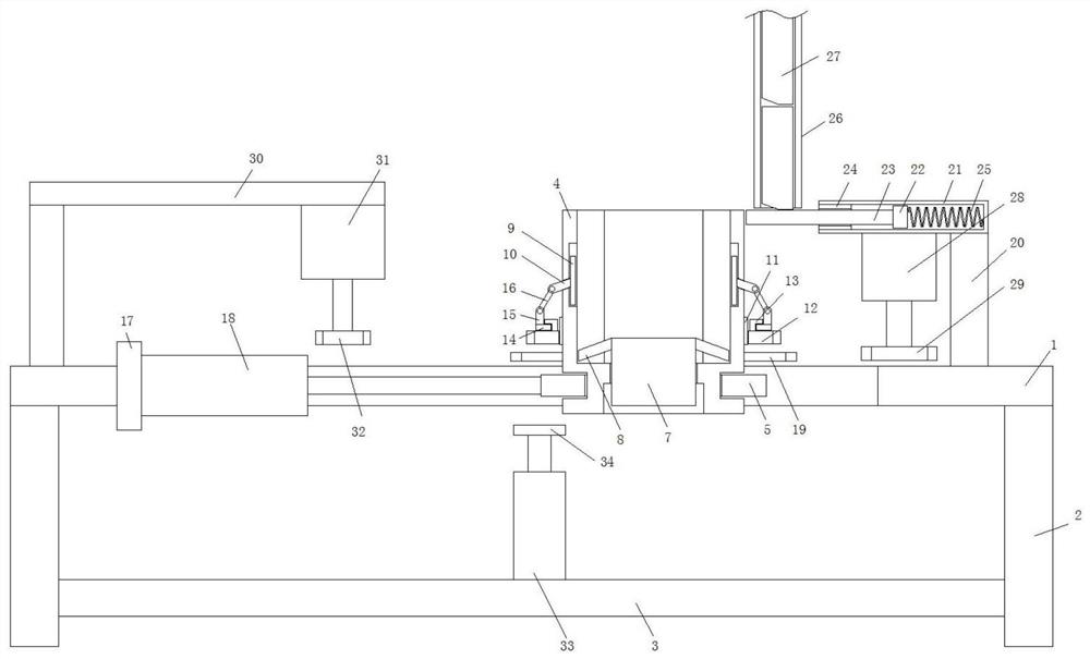
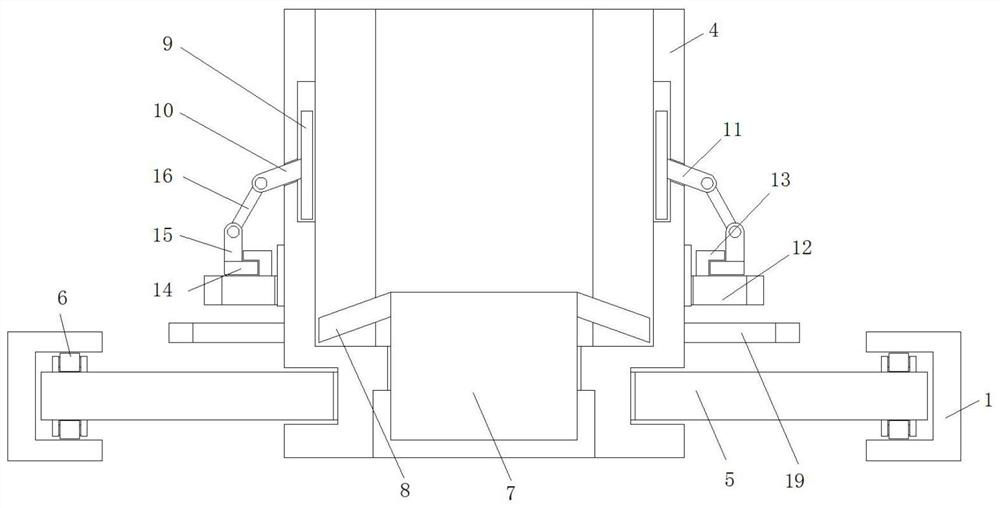
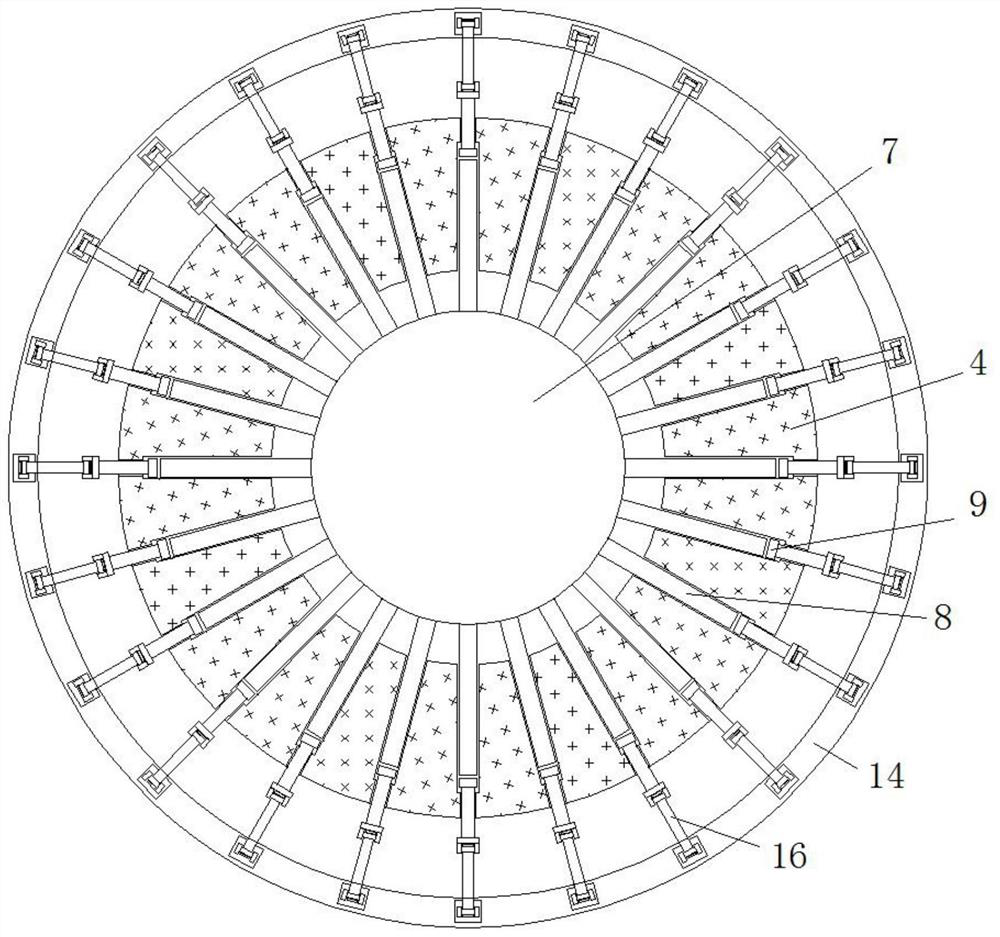
[0022] refer to Figure 1-3 , a positioning device for assembling heat dissipation fins of an evaporator, including a workbench 1, feet 2 are fixedly connected to the four corners of the bottom of the workbench 1, a partition 3 is arranged between the feet 2, and the partition 3 is horizontally arranged on the workbench 1 Vertically below the workbench 1 is provided with a vertical through hole, and the inner walls on both sides of the vertical through hole are provided with track chutes, the vertical through hole is provided with a positioning cylinder 4, and the outer wall of the positioning cylinder 4 is provided with a The annular groove and the rotating sleeve are provided with a rail slide 5, the two sides of the rail slide 5 respectively extend into the track chute, and the top side and the bottom four corners of the rail slide 5 are provided with pulleys 6, and the top of the positioning cylinder 4 is an opening structure, and the inner wall of the positioning cylinder...

Embodiment 2

[0026] Such as Figure 1-3As shown, this embodiment is basically the same as Embodiment 1. Preferably, the inner wall of one side of the vertical through hole is fixedly connected with a mounting plate 17, and one side of the mounting plate 17 is fixed with a cylinder one 18 by bolts, and the cylinder one The output bar of 18 is fixedly connected with one side of track slide plate 5.

[0027] In this embodiment, the setting of cylinder one 18 is to drive the horizontal movement of the track slide 5 , so as to complete the conversion of the station of the positioning cylinder 4 .

Embodiment 3

[0029] Such as Figure 1-3 As shown, this embodiment is basically the same as Embodiment 1. Preferably, the top side of the partition plate 3 is fixed with a cylinder 2 33 by bolts, and the output rod of the cylinder 2 33 is fixedly connected with a bottom push plate 34, and the bottom push plate 34 Matches the underside of the sliding base 7.

[0030] In this embodiment, the second cylinder 33 pushes the fin plate 27 on the top of the sliding base 7 and the top of the cylindrical utensil to protrude from the top of the positioning cylinder 4 through the bottom push plate 34 .


PUM


Abstract

The invention discloses a positioning device for assembling heat-dissipating fin plates of an evaporator, which includes a workbench, the four corners of the bottom of the workbench are fixedly connected with feet, and partitions are arranged between the feet, and the partitions are horizontally arranged on the workbench Vertically below, the workbench is provided with a vertical through hole, the inner walls of both sides of the vertical through hole are provided with rail slide grooves, a positioning cylinder is arranged in the vertical through hole, and the outer wall of the positioning cylinder is provided with a There is an annular groove and a track slide is set on the rotating sleeve. The two sides of the track slide extend into the track chute respectively, and the top and bottom corners of the track slide are equipped with pulleys. The top of the positioning cylinder is an opening. structure, and the inner wall of the positioning cylinder is provided with several fin placement grooves arranged at equal distances, and the bottom of the positioning cylinder is provided with round holes. The invention saves manpower, improves production efficiency, ensures positioning effect, improves safety, and satisfies people's use requirements in production and life.

Description

technical field [0001] The invention relates to the technical field of evaporators, in particular to a positioning device for assembling heat dissipation fins of an evaporator. Background technique [0002] An important heat transfer mechanism in the existing evaporator is the heat dissipation fin. The use of the heat dissipation fin greatly increases the contact area of ​​heat exchange, thereby greatly speeding up the efficiency of heat exchange. When assembling the evaporator In the process, the heat dissipation fins are manually placed on the outside of the cylindrical appliance one by one, and after local spot welding, temporary fixation is performed, and then the linear welding of the contact surface of the fins is performed, which is time-consuming and laborious, especially In the process of manually jacking up the fin plate and spot welding, people's hands are often burned, which cannot meet the needs of people in production and life. Contents of the invention [0...

Claims


Application Information

Patent Timeline
Patent Type & Authority Patents(China)
IPC IPC(8): B23K37/04
CPCB23K37/0443
Inventor 沈必亮王晓春
Owner ANHUI CHUNHUI INSTR CABLE GROUP
Why Eureka
Try Eureka