
A motor bearing precision mounting machine

A technology for installing machines and motors, applied in metal processing equipment, metal processing, manufacturing tools, etc., can solve the problems of low work efficiency, labor, and high labor intensity, and achieve good installation quality, improved quality, and improved work efficiency. Effect

Active Publication Date: 2021-01-15
无锡市极光电动科技有限公司
View PDF12 Cites 0 Cited by
  • Summary
  • Abstract
  • Description
  • Claims
  • Application Information

AI Technical Summary

Problems solved by technology

[0004] The above technical solution adopts a manual method to press, although it can make the bearing accurately correspond to the end cover of the motor, but the installation process is laborious, labor-intensive, and work efficiency is low

Method used


Image

  • A motor bearing precision mounting machine
  • A motor bearing precision mounting machine
  • A motor bearing precision mounting machine

Examples


Embodiment

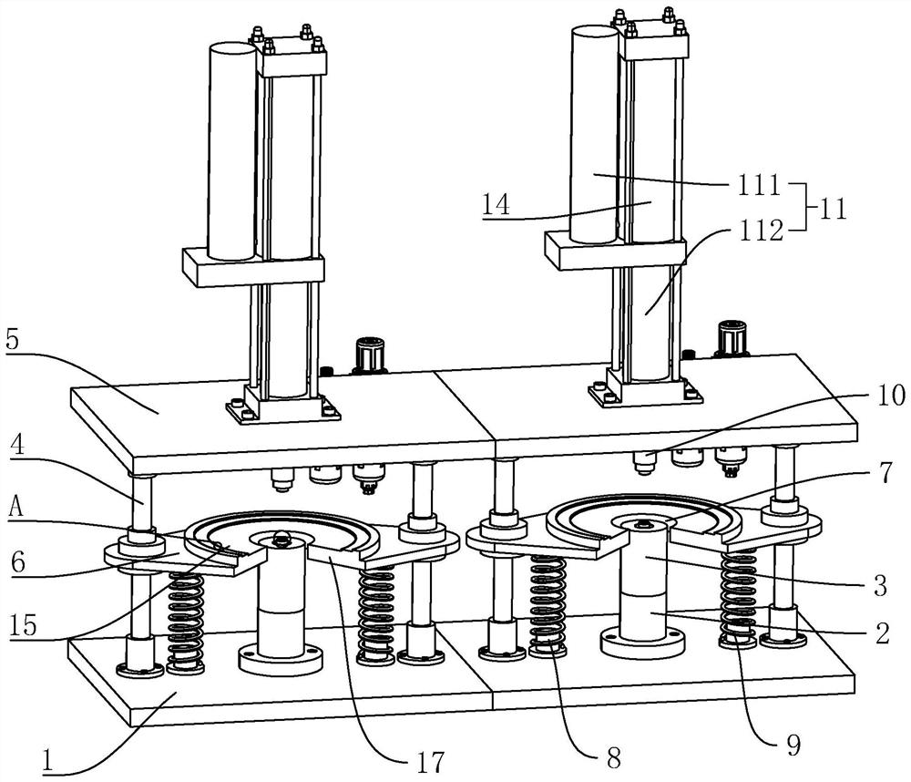
[0034] Example: a precision mounting machine for motor bearings, such as figure 1 As shown, including a support frame 1, the upper end of the support frame 1 is fixedly connected with four guide support rods 4, wherein every two guide support rods 4 are a group, and the upper end of each group of guide support rods 4 is fixedly connected with a support plate 5 , an end cover placing plate 6 is arranged between the support plate 5 and the upper end face of the support frame 1, the end cover placing plate 6 is slidably connected between the two guiding support rods 4, and the center position of the end cover placing plate 6 is provided with an installation slot 7. The upper end of the support plate 5 is provided with a drive mechanism 11, and the drive mechanism 11 is linked with a pressing punch 10. The pressing punch 10 is slidably inserted on the support plate 5 and is arranged opposite to the end cover placement plate 6. The support frame 1 The upper end is provided with a b...

specific Embodiment approach

[0042] Specific implementation: firstly, the sealing ring is sleeved on the outer side of the fixed rod 13, then the bearing is placed on the upper end of the bearing placing table 3, and finally the motor end cover is placed on the upper end of the end cover placing plate 6, and then the cylinder 14 is activated, and the piston of the cylinder 14 The rod is linked with the piston rod of the second oil cylinder 112, and the piston rod of the second oil cylinder 112 is linked with the pressing punch 10, so that the pressing punch 10 drives the sealing ring to move down quickly, the sealing ring can be quickly installed in the end cover, and then the first An oil cylinder 111 makes the first oil cylinder 111 link with the second oil cylinder 112, so that the pressing punch 10 can continue to abut the end cover, so that the bearing can be accurately installed in the end cover, and the sealing ring and the bearing can be installed.


PUM


Abstract

The invention relates to a precise mounting machine for a motor bearing. The machine comprises a supporting frame, the upper end of the support frame is fixedly connected with four guide supporting rods; every two guide supporting rods are arranged in a group; the upper ends of each group of guide supporting rods are fixedly connected with a supporting plate; an end cover placing plate is arrangedbetween the supporting plate and the upper end surface of the supporting frame; the end cover placing plate is connected between the two guide supporting rods in a sliding mode, a mounting groove isformed in the center of the end cover placing plate, a driving mechanism is arranged at the upper ends of the supporting plates, the driving mechanism is in linkage with an abutting punch, the abutting punch is inserted into the supporting plates in a sliding mode and is opposite to the end cover placing plate, and a bearing containing table is arranged at the upper end of the supporting frame. When the bearing is installed, the bearing is placed on the bearing containing table, the end cover is placed on the end cover placing plate, and then the driving mechanism is started and is enabled tobe in linkage with the abutting punch, so that the abutting punch downwards abuts against the end cover, the end cover abuts against the bearing, and the bearing and the end cover are installed.

Description

technical field [0001] The invention relates to the technical field of electric vehicle motor production equipment, in particular to a precision mounting machine for motor bearings. Background technique [0002] Bearings are used to determine the relative movement position of the rotating shaft and other parts, and play a supporting or guiding role. The main function of the bearing is to support the rotating shaft or other moving bodies, guide the rotation or movement, and bear the load transmitted by the shaft or the parts on the shaft. Bearings are an indispensable basic component in contemporary machinery and equipment. Its accuracy, performance, life and reliability play a decisive role in the accuracy, performance, life and reliability of the main engine, and are widely used in various industries of the national economy. . The motor equipment industry also needs to use bearings such as rolling bearings and sliding bearings to assist the rotation of the motor rotor, bu...

Claims


Application Information

Patent Timeline
Patent Type & Authority Patents(China)
IPC IPC(8): B23P19/027
CPCB23P19/027
Inventor 于国刚
Owner 无锡市极光电动科技有限公司
Learn More