
A rotary positioning device

A positioning device and positioning pin technology, used in positioning devices, large fixed members, manufacturing tools, etc., can solve the problems of difficult to ensure processing quality of combined fixtures, unsuitable for mass production, long tooling preparation cycle, etc., to improve processing quality and Efficiency, simple processing technology scheme, lightening effect of light work

Active Publication Date: 2022-01-14
JINCHENG NANJING ELECTROMECHANICAL HYDRAULIC PRESSURE ENG RES CENT AVIATION IND OF CHINA
View PDF10 Cites 0 Cited by
  • Summary
  • Abstract
  • Description
  • Claims
  • Application Information

AI Technical Summary

Problems solved by technology

In the preliminary solution, the construction plan of combined fixtures (that is, each processing hole corresponds to a set of special fixtures) is adopted, but the limitations of combined fixtures make it unsuitable for mass production. When the positioning accuracy of products is high, combined fixtures are very difficult. It is difficult to guarantee the stability of the processing quality, and the number of connecting holes of the steering gear housing is large, and each hole has different inclination angles and processing surface requirements, which leads to the need for a pair of combined fixtures for each hole to be processed in actual processing. Guarantee the accuracy of its angular position, so that the actual number of tooling required is large and the tooling preparation period is long

Method used


Image

  • A rotary positioning device
  • A rotary positioning device
  • A rotary positioning device

Examples


Embodiment Construction

[0028] In order to better illustrate the present invention, it will be described in detail below in conjunction with the accompanying drawings.

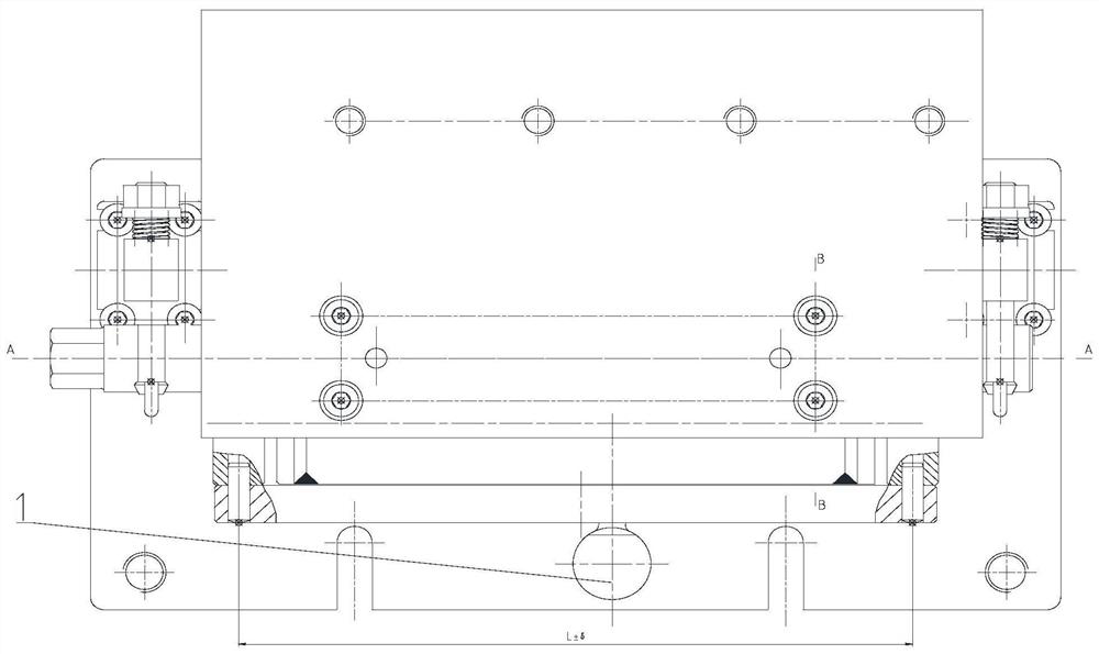
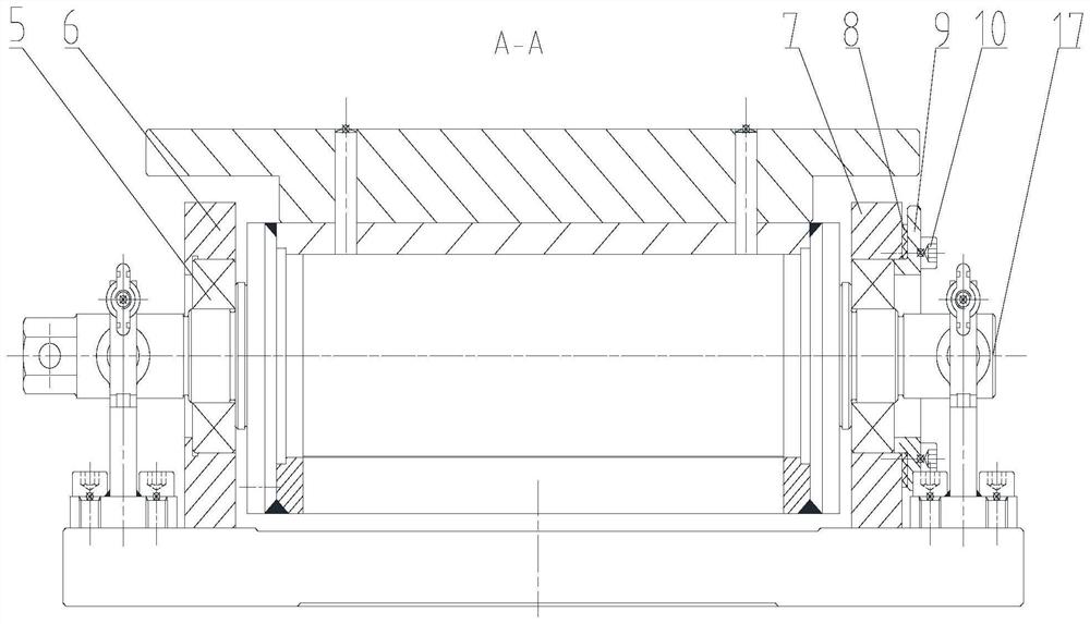
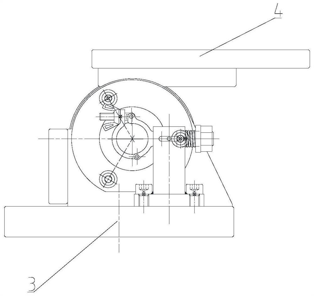
[0029] see figure 1 , figure 2 , Figure 5 , which is a structural schematic diagram and structural implementation of the present invention. The structure includes positioning pin 1, bottom plate 3, product placement plate 4, left support plate 6, right support plate 7, limit assembly, clamp assembly 11, positioning panel 12, roller assembly 17; left support plate 6, right support After the plates 7 are mounted on the two ends of the drum assembly 17 respectively, the left support plate 6 and the right support plate 7 are fixed on the base plate 3, and the positioning panel 12 is installed on the vertical surface of one side of the left support plate 6 and the right support plate 7, The product placement plate 4 is installed on the plane P of the drum assembly 17, and a clamp assembly 11 is fixedly installed at both ends of the b...


PUM


Abstract

The invention belongs to a clamping structure for special processing, in particular to a rotary positioning device. The structure includes a positioning pin (1), a bushing (2), a bottom plate (3), a product placement plate (4), a left support plate (6), a right support plate (7), a clamp assembly (11), and a positioning panel (12), drum assembly (17). The present invention realizes the preset angle positioning of the drum (17) by installing the positioning pin (1) on the positioning panel (12). The rotary positioning structure solves the problem of multi-angle rapid processing and positioning of complex non-array distributed hole systems. This positioning method can actually meet the requirements of different processing angle changes and fast positioning of processed products. During the processing, the fixing method of the fixture is the clamp type, and the adjustment method is the rotation method, which greatly reduces the workload of the operator and greatly improves the processing quality and efficiency.

Description

technical field [0001] The invention belongs to a clamping structure for special processing, in particular to a rotary positioning device. Background technique [0002] The processing of products with multi-processing surfaces and multi-angle connecting holes, due to the high processing accuracy requirements, cannot be met by conventional processing methods such as fitters, and special processing solutions are required. In order to solve the special processing problems of this type of product, it is necessary to design a special clamping structure. In the preliminary solution, the construction plan of combined fixtures (that is, each processing hole corresponds to a set of special fixtures) is adopted, but the limitations of combined fixtures make it unsuitable for mass production. When the positioning accuracy of products is high, combined fixtures are very difficult. It is difficult to guarantee the stability of the processing quality, and the number of connecting holes o...

Claims


Application Information

Patent Timeline
Patent Type & Authority Patents(China)
IPC IPC(8): B23Q3/06B23Q1/25
CPCB23Q3/06B23Q1/25
Inventor 张智森唐厚继戴延丰
Owner JINCHENG NANJING ELECTROMECHANICAL HYDRAULIC PRESSURE ENG RES CENT AVIATION IND OF CHINA
Learn More