

Phase change heat preservation box, heat preservation testing method, and manufacturing method of heat preservation structure
An incubator and phase change technology, which is used in thermal insulation containers, household refrigeration devices, investigation stages/state changes, etc., can solve the problems of inability to reuse and recycle phase change materials, difficulties, etc., and achieve improved thermal insulation effect, reasonable structure, and improved The effect of thermal conductivity
- Summary
- Abstract
- Description
- Claims
- Application Information
AI Technical Summary
Problems solved by technology
Method used
Image

Examples
Embodiment 1
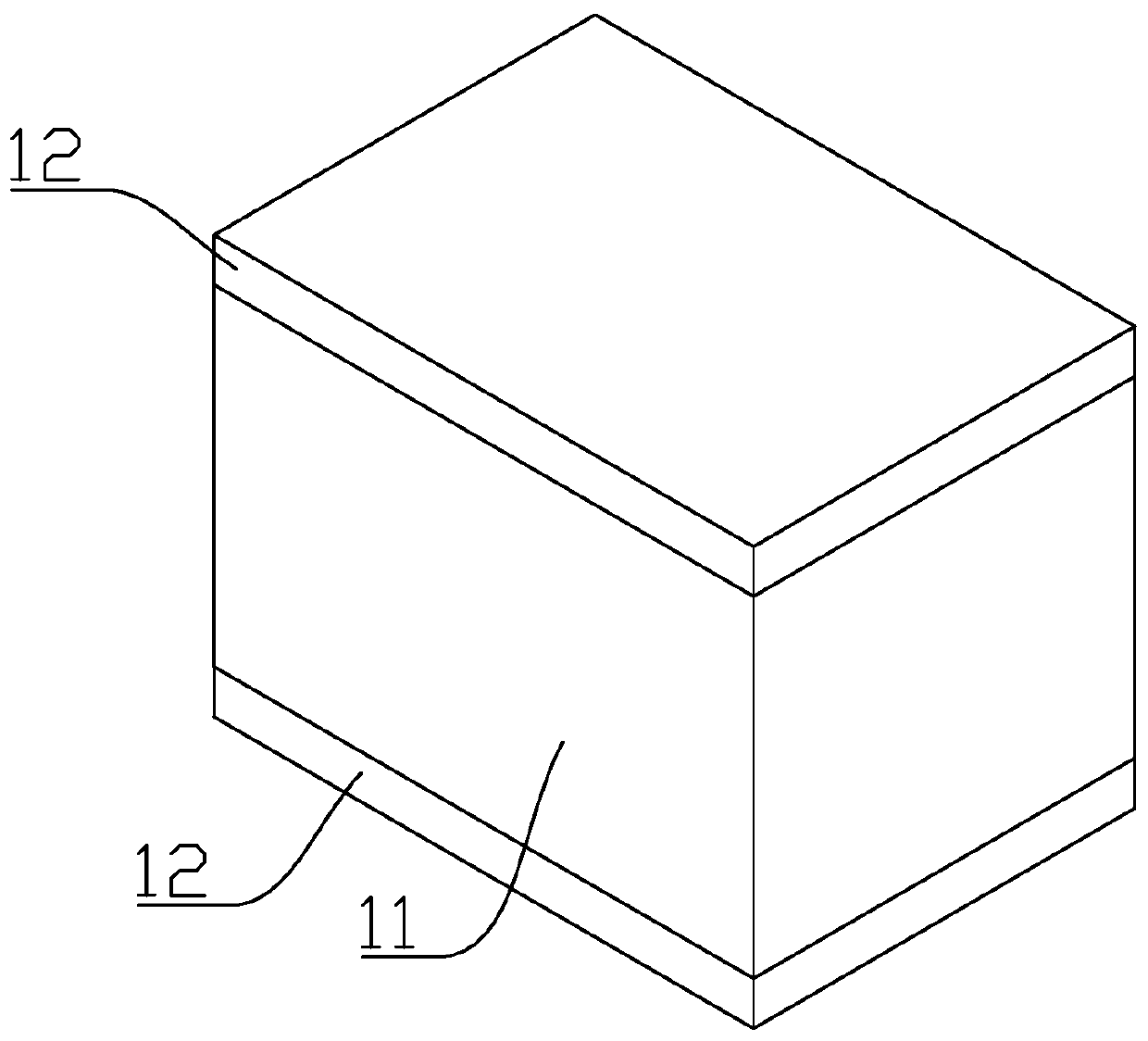
[0022] The present invention relates to a phase change incubator, which includes a box body 11 . The upper bottom surface, the lower bottom surface and the side walls of the box body 11 are respectively arranged with thermal insulation structures, and the thermal insulation structures are respectively installed as modular structures. The thermal insulation structure located on the upper bottom surface and the lower bottom surface of the box body 11 is a paraffin thermal insulation structure 12, and the paraffin thermal insulation structure 12 is a phase change material. The paraffin thermal insulation structure 12 includes paraffin microcapsules and heat-conducting silica gel, and the paraffin microcapsules and heat-conducting silica gel are mixed and stirred evenly. The composite material obtained by mixing paraffin microcapsules and heat-conducting silica gel has high heat conduction efficiency, good heat preservation effect, and can be reused many times.
[0023] The paraff...
Embodiment 2
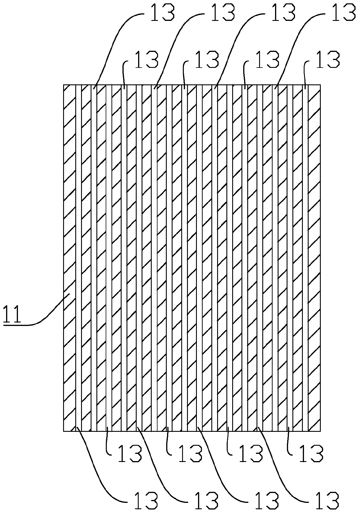
[0034]The difference between this embodiment and Embodiment 1 is that the insulation structure located on the side wall of the box body 11 is a paraffin cylinder insulation structure, the paraffin cylinder insulation structure is a phase change material, and the paraffin cylinder insulation structure includes paraffin and heat-conducting silica gel, paraffin and The heat-conducting silica gel is mixed and stirred evenly, and the composite material obtained by mixing paraffin wax and heat-conducting silica gel has high material conduction efficiency, good heat preservation effect, and can be reused many times. The mixed composite material is injected into the cavity of the cuboid, and the composite material of paraffin wax and heat-conducting silica gel is modularly designed as a columnar thermal insulation structure 13, which can avoid the thermal conductivity difference caused by directly using the phase change material to make the box 11 And problems such as being unable to r...
PUM
 Abstract
Description
Claims
Application Information