Vanadium slag continuous vanadium solution leaching device

A leaching and solution technology, applied in the field of vanadium slag continuous leaching vanadium solution device, can solve the problems of long time and complicated procedures, and achieve the effect of improving the reaction speed

Pending Publication Date: 2019-12-03
PANZHIHUA UNIV
View PDF0 Cites 4 Cited by
  • Summary
  • Abstract
  • Description
  • Claims
  • Application Information

AI Technical Summary

Problems solved by technology

The traditional leaching method takes a long time, the temperature of the leaching solution and the solid-liquid ratio are strictly controlled, and the procedure is cumbersome

Method used


Image

  • Vanadium slag continuous vanadium solution leaching device
  • Vanadium slag continuous vanadium solution leaching device
  • Vanadium slag continuous vanadium solution leaching device

Examples


Embodiment 1

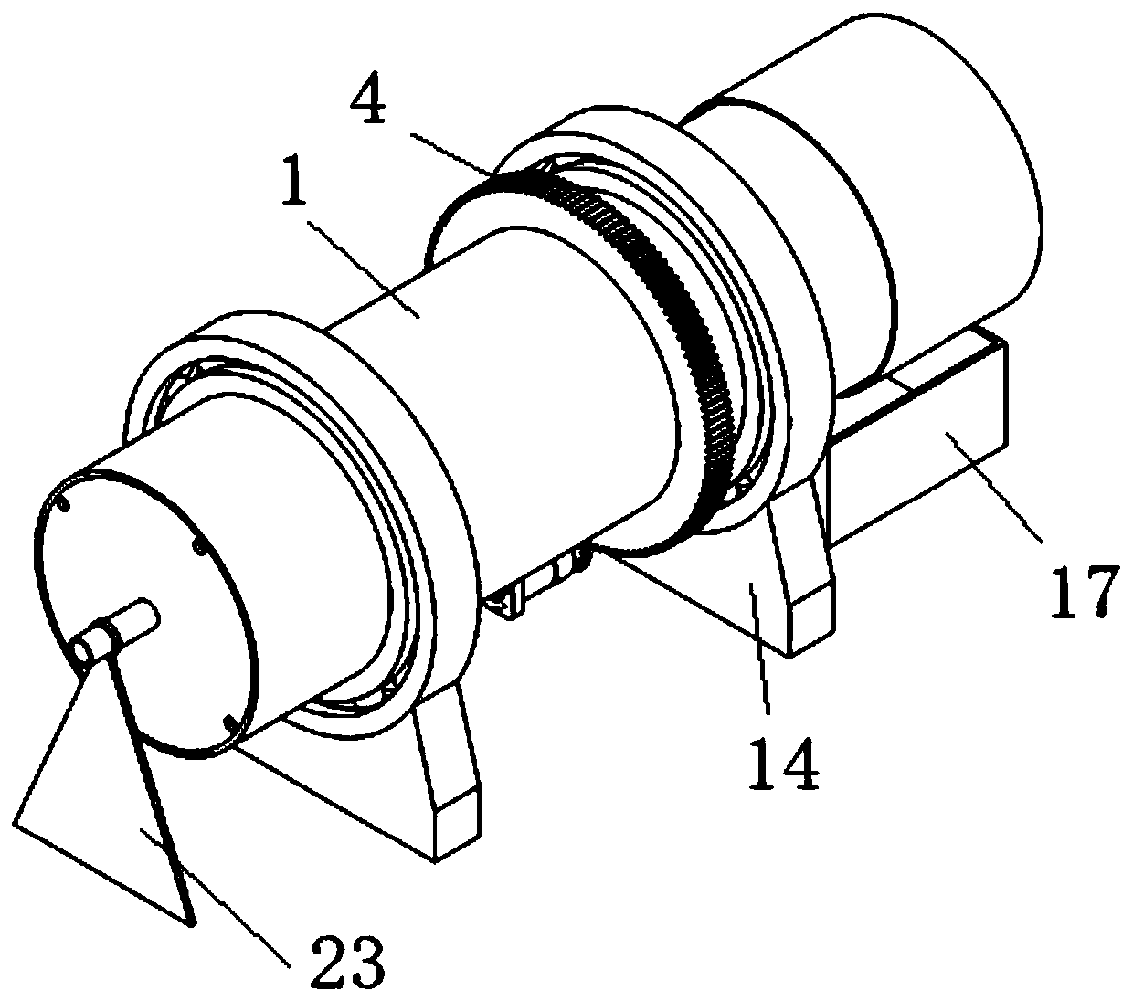
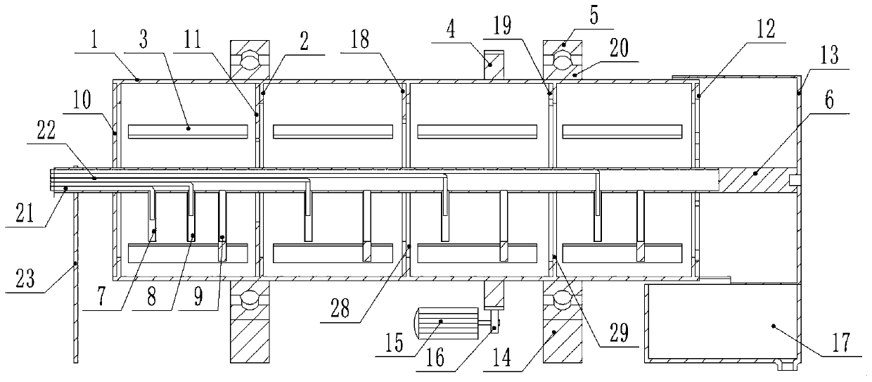
[0037] Such as figure 1 and 2 As shown, a vanadium slag continuous leaching vanadium solution device includes a rotary cylinder 1, the outer edge of the rotary cylinder 1 is provided with a rotating support assembly, and the outer edge of the rotary cylinder 1 on one side of the rotary support assembly is provided with a The driving assembly used to drive the rotation of the rotary cylinder 1; one end of the rotary cylinder 1 is provided with a discharge port 26, and the interior of the rotary cylinder 1 is provided with a cavity, and a central shaft is arranged in the cavity along the axial direction 6. There are several baffles arranged at intervals in the cavity, and the middle part of the baffle is provided with a through hole 24 sleeved on the central shaft 6, from the direction away from the discharge port 26 to the direction close to the discharge port. The aperture of the via hole 24 on the baffle plate in the direction of the material outlet 26 increases successively...

Embodiment 2

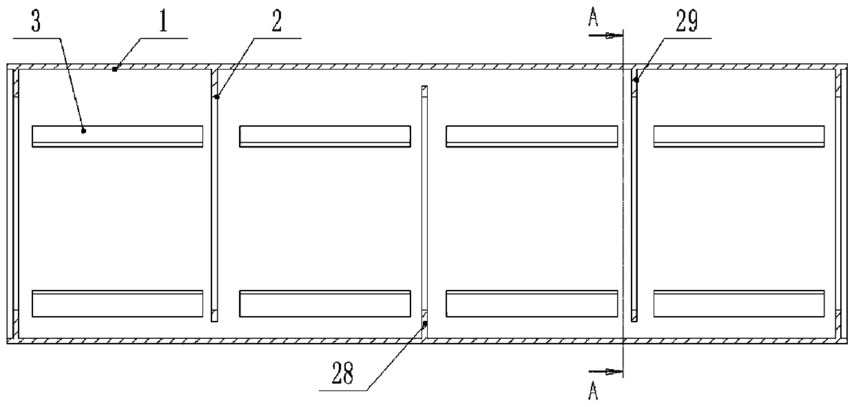
[0044] Such as image 3 As shown, this implementation is further optimized on the basis of Embodiment 1. This embodiment focuses on the improvements compared with Embodiment 1, and the similarities will not be repeated. In this embodiment, the rotating cylinder 1 includes a front baffle 10, a rear baffle 12, and a continuous side wall sealingly connected between the front baffle 10 and the rear baffle 12. The discharge port 26 is opened on the rear baffle 12, and the discharge port 26 is fan-shaped. Such as Figure 5 As shown, there are 4 discharge ports 26 and the central angles of the 4 fan-shaped discharge ports 26 are all set towards the center of the tailgate 12. Offer 4 fan-shaped discharge openings 26 on the rear baffle plate 12, be convenient to the vanadium solution to flow out, because the rotary cylinder 1 is always rotating, can guarantee the discharge rate of the rotary cylinder 1 when rotating like this.

Embodiment 3

[0046] Such as figure 2 As shown, this implementation is further optimized on the basis of Embodiment 2. This embodiment focuses on the improvements compared with Embodiment 1, and the similarities will not be repeated. In this embodiment, the front baffle 10 and the center of the rear baffle 12 are provided with a through central hole, and one end of the central shaft 6 passes through the central hole of the front baffle 10 and is connected with a bracket 23 arranged outside the cavity, and the central shaft 6 is connected to the front baffle. The central hole of the plate 10 is connected with the sealing shaft, the other end of the central shaft 6 runs through the central hole of the tailgate 12 and is connected with the tail cover 13 sleeved outside the rotating cylinder 1, and the central shaft 6 is connected to the center of the tailgate 12. Bore sealed shaft connection. This can ensure that the rotary cylinder 1 is rotating, and the central shaft 6 remains motionless, ...


PUM


Abstract

The invention discloses a vanadium slag continuous vanadium solution leaching device, and belongs to the technical field of metal smelting. The device comprises a rotary drum body, a rotary supportingassembly is arranged on the outer edge of the rotary drum body, and a driving assembly used for driving the rotary drum body to rotate is arranged on the outer edge of the rotary drum body on one side of the rotary supporting assembly; a discharge hole is formed in the end part of one side of the rotary cylinder body; a cavity is formed in the rotary cylinder body; a central shaft rod is arrangedin the cavity along the axial direction; a plurality of baffles arranged at intervals are arranged in the cavity, through holes formed in the center shaft rod in a sleeving mode are formed in the middles of the baffles, the hole diameters of the through holes in the baffles are sequentially increased from the direction away from the discharging hole to the direction close to the discharging hole,and the hole diameter of the through hole formed in the baffle farthest away from the discharging hole is larger than the diameter of the center shaft rod. According to the device, acid adding continuous leaching is adopted, and acid adding continuous leaching comprises the steps that acid is continuously added into each leaching stirring tank, and mixing is continuously conducted till the leaching reaction is completed. The device is simple in process and short in reaction time.

Description

technical field [0001] The invention relates to the technical field of metal smelting, in particular to a continuous vanadium slag leaching vanadium solution device. Background technique [0002] Vanadium has many excellent physical and chemical properties, so vanadium has a wide range of uses and is known as the metal "vitamin". Extracting vanadium from vanadium slag has many technical difficulties in traditional extraction methods. [0003] The traditional extraction method of vanadium in vanadium slag is sodium roasting of vanadium slag-water immersion. The principle of vanadium slag sodium roasting-water immersion is to use vanadium slag as raw material and sodium carbonate as redox agent to convert V2O3 in vanadium slag into sodium vanadate through high-temperature roasting, that is, to convert trivalent vanadium in vanadium slag It is pentavalent vanadium, and then added to industrial water for leaching to obtain sodium vanadate solution. Factors affecting the leach...

Claims


Application Information

Patent Timeline
Patent Type & Authority Applications(China)
IPC IPC(8): C22B3/02C22B3/06C22B34/22
CPCC22B3/02C22B3/06C22B34/22Y02P10/20
Inventor 郑彬杨宽
Owner PANZHIHUA UNIV
Why Eureka
Try Eureka