Check patentability & draft patents in minutes with Patsnap Eureka AI!

Equipment for construction of bridge floor waterproof layer

A waterproof layer and equipment technology, applied in bridge construction, bridges, erection/assembly of bridges, etc., can solve the problems of water accumulation, reduced functional effect of concrete protective layer, different degrees of concrete compaction, etc., to meet the vertical and horizontal drainage slope, High construction efficiency and good drainage effect

Pending Publication Date: 2019-12-03
中铁大桥局集团第六工程有限公司
View PDF0 Cites 0 Cited by
  • Summary
  • Abstract
  • Description
  • Claims
  • Application Information

AI Technical Summary

Problems solved by technology

[0003] At present, in the construction of the waterproof protective layer of the high-speed railway, it is necessary to construct the waterproof layer on the surface of the bridge beam between the two rows of ballastless track slabs. The laying amount of polymer asphalt waterproofing membrane is large, the efficiency of manual laying is relatively low, and the laying quality cannot be guaranteed
In addition, the construction method of concrete is to vibrate manually with small vibrating rods, vibrating every other place, which is prone to leakage vibration, and manual vibrating cannot accurately grasp the vibrating time, because the vibrating time of each place is different, resulting in dense concrete The degree is different, and the overall quality is uneven; after vibrating, it is still necessary to manually close the surface, manually control the concrete elevation and manually control the drainage slope, but the artificial surface cannot accurately control the concrete elevation and the drainage slope of the top surface of the concrete protective layer, and the slope will often occur. The phenomenon that meets the design requirements will greatly reduce the functional effect of the concrete protective layer, and water accumulation will occur between the lines, which does not meet the drainage requirements

Method used


Image

  • Equipment for construction of bridge floor waterproof layer
  • Equipment for construction of bridge floor waterproof layer
  • Equipment for construction of bridge floor waterproof layer

Examples


Embodiment Construction

[0045] The present invention will be described in further detail below in conjunction with the accompanying drawings and embodiments.

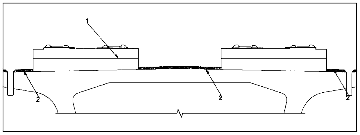
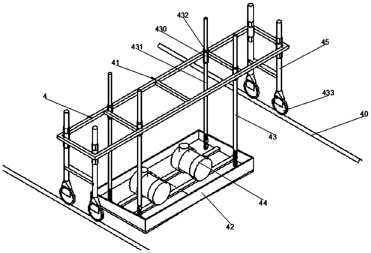
[0046] see figure 1 As shown, the embodiment of the present invention provides a kind of equipment for the construction of bridge deck waterproof layer, which is used for the bridge deck 2 between two adjacent rows of ballastless tracks 1 and the bridge between the ballastless track 1 and the protective wall. Surface 2 is used for construction, the asphalt coil 7 is first laid, and then concrete is poured on the asphalt coil 7 to form a waterproof layer. After the concrete is poured, the concrete vibrating device 4 is used to vibrate the concrete and close the surface, see figure 2 As shown, the concrete vibrating device 4 includes two slide rails 40, a support frame 41, a vibrating table 42 and a driver 44. When the bridge deck 2 between two adjacent rows of ballastless tracks 1 is constructed, the two slide rails The rail 40 is set on two ...


PUM


Abstract

The invention discloses equipment for construction of a bridge floor waterproof layer. The equipment is applied to construction of a bridge floor between two adjacent rows of ballastless tracks and abridge floor between each ballastless track and a protecting wall. The equipment comprises a concrete vibrating device, wherein the concrete vibrating device comprise two sliding rails, a support frame, a vibrating table and a driver; the two sliding rails are used for being arranged on the two rows of ballastless tracks or the ballastless tracks and the protecting wall respectively; the support frame is transversely arranged between the two sliding rails, and the two ends of the support frame are movably arranged on the two sliding rails respectively; the shape of the bottom surface of the vibrating table is matched with that of the bridge floor, the vibrating table is connected to the bottom of the support frame through a height adjusting mechanism, and the height adjusting mechanism isused for adjusting height of the vibrating table; the driver is arranged on the vibration table and used for driving the vibrating table to vibrate, so as to vibrate the concrete layer on the bridge floor. Uniform vibration of concrete can be realized rapidly, leaking vibration can be avoided, requirements for concrete elevation and drainage slope of the concrete top surface are met, and the quality of the bridge floor waterproof layer is guaranteed.

Description

technical field [0001] The invention relates to the field of bridge construction, in particular to a device for construction of a bridge deck waterproof layer. Background technique [0002] Ballastless track concrete bridge deck waterproof layer is a major link to improve bridge durability. High-speed rail ballastless track adopts a waterproof system composed of coiled asphalt waterproof layer and C40 fine stone fiber concrete or C40 reinforced concrete protective layer. [0003] At present, in the construction of the waterproof protective layer of the high-speed railway, it is necessary to construct the waterproof layer on the surface of the bridge beam between the two rows of ballastless track slabs. The laying quantity of polymer bitumen waterproofing membrane is large, the efficiency of manual laying is relatively low, and the laying quality cannot be guaranteed. In addition, the construction method of concrete is to vibrate manually with small vibrating rods, vibrating...

Claims


Application Information

Patent Timeline
IPC IPC(8): E01D21/00
CPCE01D21/00
Inventor 高光品张涛马志成张三刚武立冬王海龙
Owner 中铁大桥局集团第六工程有限公司
Features
  • R&D
  • Intellectual Property
  • Life Sciences
  • Materials
  • Tech Scout
  • Unparalleled Data Quality
  • Higher Quality Content
  • 60% Fewer Hallucinations
Learn More