
Prefabricated pile

A technology of prefabricated piles and pile sections, applied in sheet pile wall, construction, foundation structure engineering, etc., can solve problems such as increasing the length or outer diameter of the pipe pile, small friction between the pile body and the soil body, and increasing the cost of the pile foundation project. , to achieve the effect of enhancing the pull-out bearing performance, the close fit effect, and the increase of the specific surface area.

Inactive Publication Date: 2019-12-03
周兆弟
View PDF10 Cites 1 Cited by
  • Summary
  • Abstract
  • Description
  • Claims
  • Application Information

AI Technical Summary

Problems solved by technology

[0003] Although this kind of circular solid prestressed concrete pipe pile has better crack resistance and seismic performance, the shortcoming of the above-mentioned circular solid prestressed concrete pipe pile is: because the outer wall surface of the concrete pile body is a smooth circular shape surface, thus resulting in less friction between the pile and the soil, when it is necessary to meet a larger axial bearing capacity or pull-out force, it is necessary to increase the length or outer diameter of the pipe pile, which will increase the overall The cost of pile foundation works
[0005] Compared with the traditional linear pipe pile, although the variable cross-section concave-convex pile with this structure has better uplift bearing capacity, in the axial projection area corresponding to the large cross-section section, due to the outer wall surface of the small cross-section pile The set of multiple ribs divides the soil around the pile body into multiple isolated arc-shaped blocks, which makes the arc-shaped blocks not closely attached to the outer wall of the small-section pile section, thus causing the pile body and the surrounding soil to The relative friction between them is limited, so the uplift bearing performance of variable cross-section concave-convex piles needs to be strengthened.

Method used


Image

  • Prefabricated pile
  • Prefabricated pile
  • Prefabricated pile

Examples


Embodiment 1

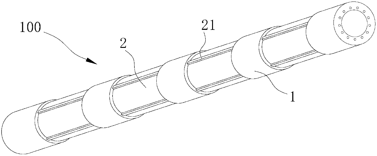
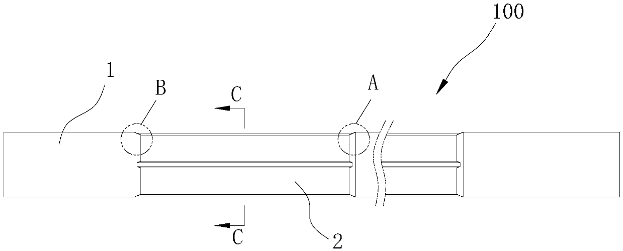
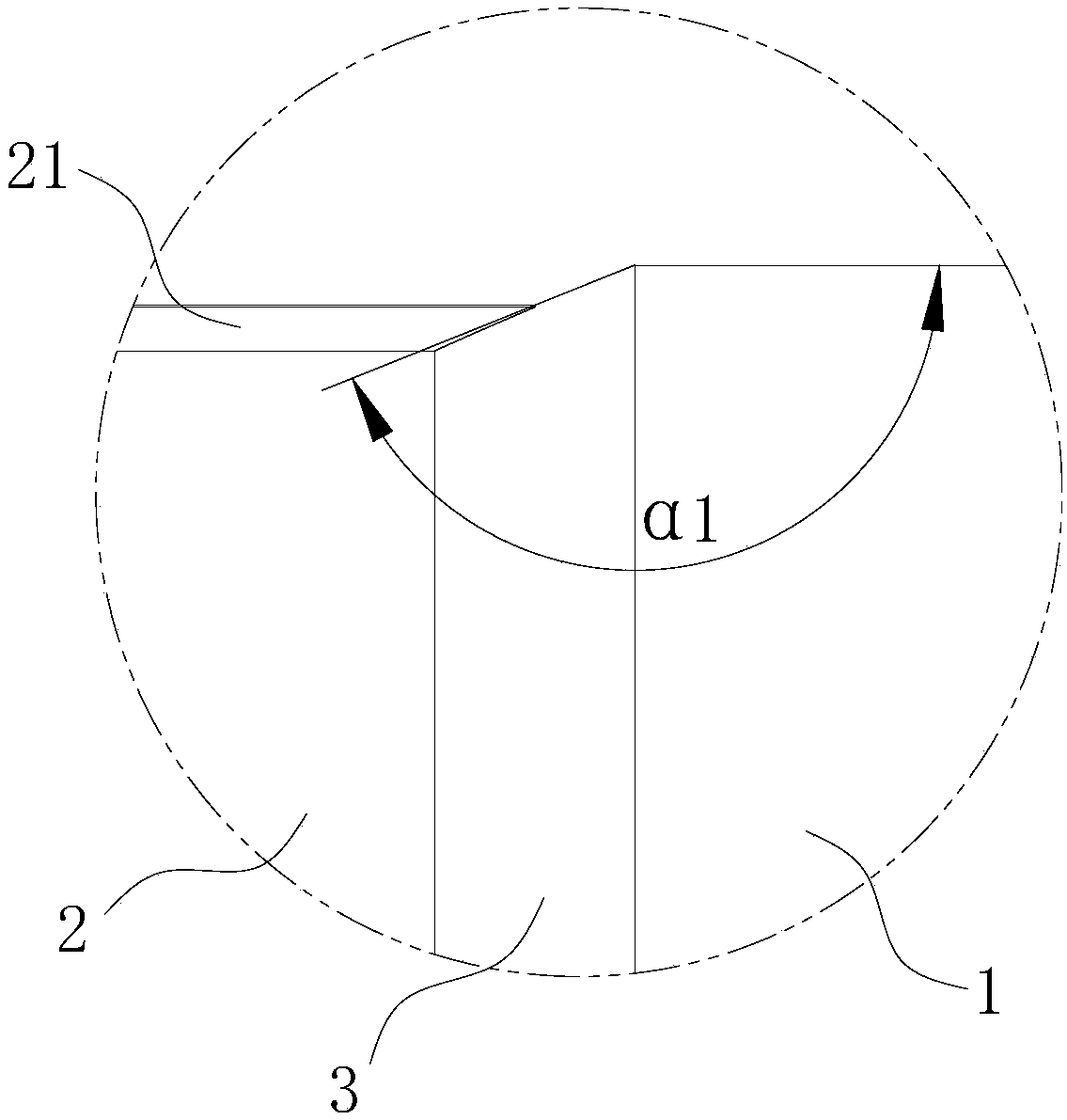
[0046] Such as figure 1 As shown, the prefabricated pile 100 provided in this embodiment is formed by pouring concrete in a mold (including an upper mold and a lower mold), and a reinforcement cage not shown in the figure is embedded in the prefabricated pile 100 . The prefabricated pile 100 includes: multi-section thick pile sections 1 and multi-section thin pile sections 2 forming an integral structure along the axial direction, and the thin pile sections 2 and thick pile sections 1 are arranged alternately along the axial direction. In this embodiment, a circular hollow prefabricated pile is taken as an example for introduction.

[0047] Of course, in the prefabricated pile 100 provided by the present invention, the prefabricated pile 100 includes at least one thin pile section 2 and at least one thick pile section 1. In the case of only one thin pile section 2 and one thick pile section 1, the In the direction from the end of the thin pile section 2 away from the thick pi...

Embodiment 2

[0058] In this embodiment, the parts that are the same as in the first embodiment are given the same reference numerals, and the same text descriptions are omitted.

[0059] Such as Figure 6 As shown, compared with Embodiment 1, the prefabricated pile 200 provided in this embodiment also has such a structure: four grooves 11 arranged around the central axis of the prefabricated pile 200 are opened on the outer peripheral wall of each thick pile section 1, and the concave The longitudinal direction of the groove 11 is consistent with the longitudinal direction of the prefabricated pile 200 . Of course, in the prefabricated pile provided by the present invention, the number of grooves 11 provided on the outer peripheral wall of the thick pile section 1 can be any number of two, three, five, six, etc., or there can be at least one thick pile section 1 is provided with a groove 11 on the outer peripheral wall. In addition, considering the end face bearing capacity of the prefab...

Embodiment 3

[0063] In this embodiment, the parts that are the same as in the first embodiment are given the same reference numerals, and the same text descriptions are omitted.

[0064] As shown in the figure, compared with the first embodiment, the prefabricated pile 300 provided by this embodiment also has such a structure: in the length direction of the prefabricated pile 300, the diameters of the outer circles of the thin pile sections 2 increase sequentially, and each thick The diameter of the outer circle of the pile segment 1 increases sequentially. Of course, in the prefabricated pile provided by the present invention, in the length direction of the prefabricated pile 100, only the outer diameter of each thin pile section 2 may increase sequentially, or only the outer diameter of each thick pile section 1 may increase sequentially. In such a structural situation, during pile sinking construction, the end of the prefabricated pile 300 with a smaller diameter is placed below and sun...


PUM


Abstract

The invention discloses a prefabricated pile. The prefabricated pile comprises at least one fine pile section and at least one thick pile section which are formed into an integrated structure in the axial direction, the circular peripheral wall of the fine pile section is annularly provided with a plurality of convex rib plates, wherein, the length direction of the rib plates is consistent with the length direction of the prefabricated pile, the radial distance from the top end surfaces of the rib plates to the central axis of the prefabricated pile is less than the exradius of the thick pilesection, and a shaft shoulder surface is formed between the fine pile section and the adjacent thick pile section. According to the structural design, the part of the fine pile section has more contact area with a surrounding soil mass, it is also guaranteed that the surrounding soil mass of the fine pile section is surrounded into an integrated structure, the surrounding soil mass is more closelyattached to the outer wall of the fine pile section, thus, the more contact area and the closer attaching effect between the fine pile section and the surrounding soil mass improve friction force between the pile body and the surrounding soil mass, and thus the uplift bearing capacity of the prefabricated pile can be greatly enhanced.

Description

technical field [0001] The invention relates to the field of concrete pipe piles, in particular to a prefabricated pile. Background technique [0002] Concrete pipe piles are basic building materials commonly used in the fields of construction, transportation, and port construction. The shape of traditional concrete pipe piles is generally a linear square pipe pile or a round pipe pile. For example, a Chinese invention patent (CN101761075A) discloses a circular Solid prestressed concrete pipe pile, the circular solid prestressed concrete pipe pile includes a solid concrete pile body and a reinforcement cage embedded in the pile body, the two ends of the concrete pile body are provided with end skirts, and the reinforcement cage is composed of Several equal-length prestressed main reinforcements and spiral reinforcements are bound together. The prestressed main reinforcements are evenly distributed on the outer wall of the concrete pile with the centerline of the concrete rod...

Claims


Application Information

Patent Timeline
Patent Type & Authority Applications(China)
IPC IPC(8): E02D5/30E02D5/48E02D5/52E02D5/54
CPCE02D5/30E02D5/48E02D5/523E02D5/54
Inventor 周兆弟
Owner 周兆弟
Learn More