Water collection and drainage device for deep foundation pit in traffic construction

A technology for drainage devices and deep foundation pits, applied in infrastructure engineering, construction, etc., can solve problems such as easy burnout, lack of protection for water pumps, damage and deformation of drainage well pipes, etc., to reduce unnecessary costs, reduce precipitation costs, and save The effect of duration

Active Publication Date: 2021-03-26
许永
View PDF7 Cites 0 Cited by
  • Summary
  • Abstract
  • Description
  • Claims
  • Application Information

AI Technical Summary

Problems solved by technology

[0008] In view of the above situation, in order to overcome the defects of the prior art, the present invention provides a water collection and drainage device for deep foundation pits in traffic construction, which effectively solves the problem that the existing dewatering wells have an impact on the excavation of foundation pits, and the dewatering well pipes are easily damaged and deformed. , After the excavation, it is necessary to set up a water collection well separately, and the water pump lacks protection and is easy to burn out

Method used


Image

  • Water collection and drainage device for deep foundation pit in traffic construction
  • Water collection and drainage device for deep foundation pit in traffic construction
  • Water collection and drainage device for deep foundation pit in traffic construction

Examples


Embodiment 1

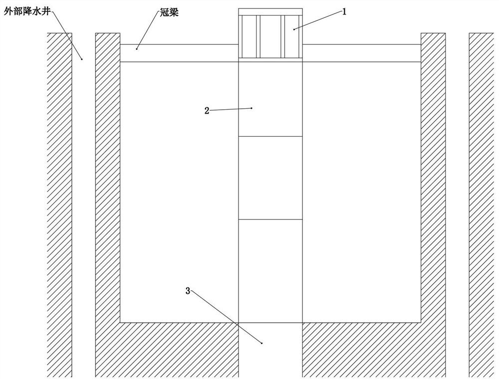
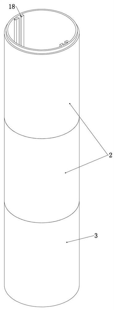
[0036] Embodiment 1, the present invention is a water collection and drainage device for a deep foundation pit in traffic construction, including a dewatering well and a dewatering well platform 1 fixedly installed on the crown beam of the foundation pit. The dewatering well platform 1 is provided with a control device that can control the hoisting The water pump in the dewatering well and the dewatering well in the foundation pit start after the foundation pit is excavated to break the pavement concrete, and it is carried out synchronously with the pouring of the crown beam. On the beam, specifically, the dewatering well platform 1 is fixed on the crown beam through expansion screws, and the water pump is hoisted from the dewatering well platform 1 to a suitable position in the dewatering well by ropes, usually directly at the base level or slightly higher than the base level position, it is characterized in that, described dewatering well comprises the upper well pipe 2 and t...

Embodiment 2

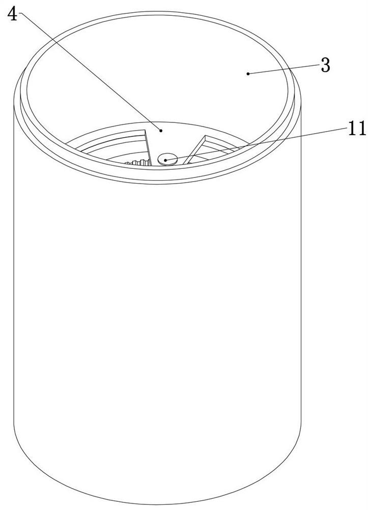
[0038] Embodiment 2. On the basis of Embodiment 1, this embodiment provides a specific structure in which the rotation of the mouthpiece 5 drives the outer shell 7 to rotate, so as to achieve the effect that the rotation of the inner shell 6 can drive the outer shell 7 to rotate synchronously, and at the same time, the inner shell can 6 and the casing 7 have different rotational speeds, so as to facilitate the cleaning of the brush 8. Specifically, the rotating structure includes an upper sun gear 10 coaxially fixedly connected with the mouthpiece 5, and the upper sun gear is engaged with a rotating connection The upper planetary gear 11 on the support frame 4, the upper planetary gear 11 is externally meshed with the upper ring gear 12 fixedly connected to the upper end surface of the housing 7, that is, the rotation of the mouthpiece 5 drives the upper sun gear 10 to rotate synchronously , so as to drive the rotation of the upper planetary gear 11 connected to the support fra...

Embodiment 3

[0039] Embodiment 3, on the basis of Embodiment 2, this embodiment provides a specific structure in which the mouthpiece 5 rotates to drive the brush 8 to rotate, so that the rotation speed of the brush 8 is different from that of the outer shell 7 and the inner shell 6, so that The brush 8, the outer shell 7, and the inner shell 6 all have relative motion. At the same time, because the outer shell 7 deposits more sediment and large particles, it is necessary for the brush 8 to have a relatively fast relative speed relative to the outer shell 7. Specifically, the The upper end surface of the shell 7 described above is rotatably connected with the lower gear ring 13, and several of the brushes 8 are fixedly connected to the lower end of the lower gear ring 13, that is, the rotation of the lower gear ring 13 can drive several brushes 8 to rotate synchronously. Figure 5 The brush 8 is set as a brush 8 with bristles only towards the side of the outer shell 7 and towards the side o...


PUM


Abstract

The invention relates to a traffic construction deep foundation pit water collecting and draining device, and effectively solves the problems of influence on excavation of a foundation pit in a traditional precipitation well, easy damage and deformation of precipitation well pipes, additional arrangement of a water collecting well after excavation and easy burnout of a water pump due to shortage of protection. The traffic construction deep foundation pit water collecting and draining device comprises a precipitation well, and a precipitation well platform fixedly mounted on a crown beam of a foundation pit; and the precipitation well platform is provided with a control device for controlling a water pump lifted in the precipitation well. The traffic construction deep foundation pit water collecting and draining device is characterized in that the precipitation well comprises multiple sections of upper well pipes communicating in sequence and lower well pipes at the lowermost ends; allthe upper well pipes are detachably connected and connected with the control device on the precipitation well platform; and a water pump protecting device is arranged in a bottom well pipe. The traffic construction deep foundation pit water collecting and draining device is simple in structure and convenient to operate, can effectively improve the precipitation quality, reduces the precipitation cost, and saves a certain construction periods.

Description

technical field [0001] The invention relates to the technical field of building construction, in particular to a water collection and drainage device for deep foundation pits in traffic construction. Background technique [0002] In urban subway construction, due to construction needs, deep foundation pits with a depth of about 30 meters or even more than 30 meters often appear in the excavation of foundation pits. In the process of deep foundation pit excavation, foundation pit precipitation is very critical. Existing deep foundation pit dewatering usually adopts dewatering wells for dewatering, which usually set some dewatering wells around the edge of the foundation pit outside the foundation pit, so that the depth of the dewatering wells is greater than the depth of the foundation pit, so as to dewater. However, this construction method is used in areas with rich groundwater resources or abundant precipitation, especially in the south, such as Guangzhou, where groundwat...

Claims


Application Information

Patent Timeline
Patent Type & Authority Patents(China)
IPC IPC(8): E02D19/06E02D19/10
CPCE02D19/06E02D19/10
Inventor 许永赵艺坡周振武姚鹏飞秦太春王燕娜刘洪杰韩子君孟昭敏
Owner 许永
Why Eureka
Try Eureka