Adjustable steel bar positioning and point distributing device

An adjustable, steel bar technology, applied in the direction of structural elements, building components, building reinforcements, etc., can solve the problems that affect the quality of steel bar binding and construction efficiency, the accuracy of manual marking positions cannot be guaranteed, and easy to produce deviations, etc., to achieve improvement Improve the quality of steel bar binding, improve the accuracy of marking, save labor and cost

Inactive Publication Date: 2019-12-03
李四喜 +1
View PDF0 Cites 1 Cited by
  • Summary
  • Abstract
  • Description
  • Claims
  • Application Information

AI Technical Summary

Problems solved by technology

[0002] In the construction of reinforcement mesh binding in various fields, such as raft reinforcement reinforcement binding, independent foundation reinforcement reinforcement binding, structural slab reinforcement binding, reinforcement mesh binding and other constructions, it is particularly important to ensure the reinforcement spacing, mesh size and adjacent plate penetration of reinforcement mesh , the usual practice is that the operator sets the position of the steel bar by drawing a ruler at a certain distance, and uses a stone pen to describe it. This operation generally requires at least two people to cooperate with the operation, and the operation is inconvenient. It is time-consuming and laborious to repeat the same work many times, and manually mark the position Accuracy cannot be guaranteed, and deviations are prone to occur, seriously affecting the quality of steel bar binding and construction efficiency

Method used


Image

  • Adjustable steel bar positioning and point distributing device
  • Adjustable steel bar positioning and point distributing device

Examples


Embodiment Construction

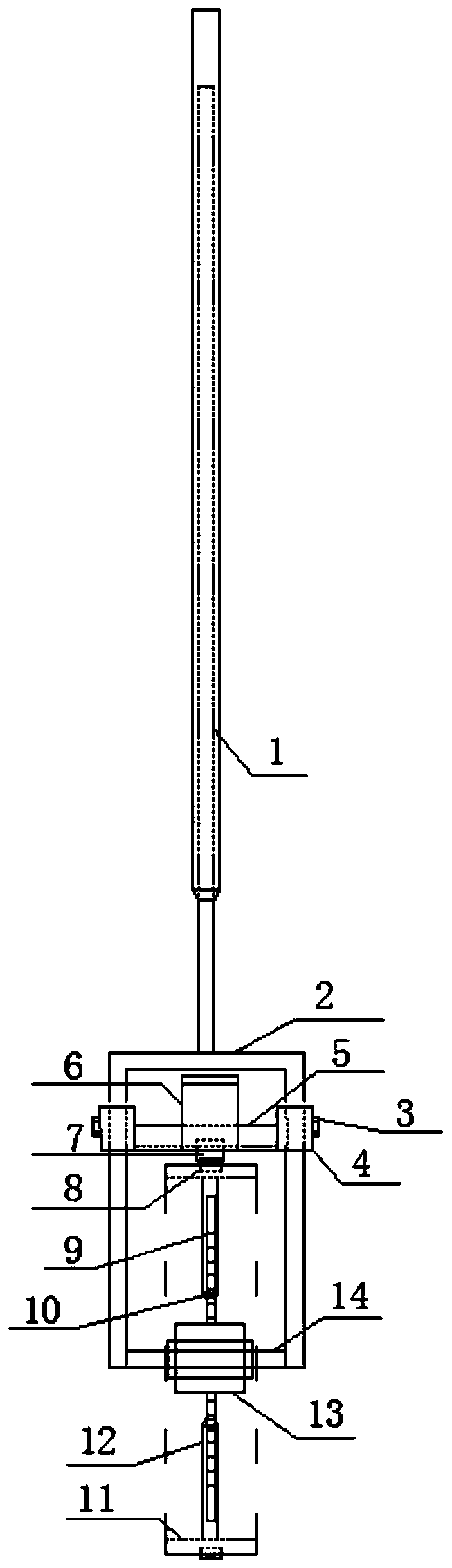
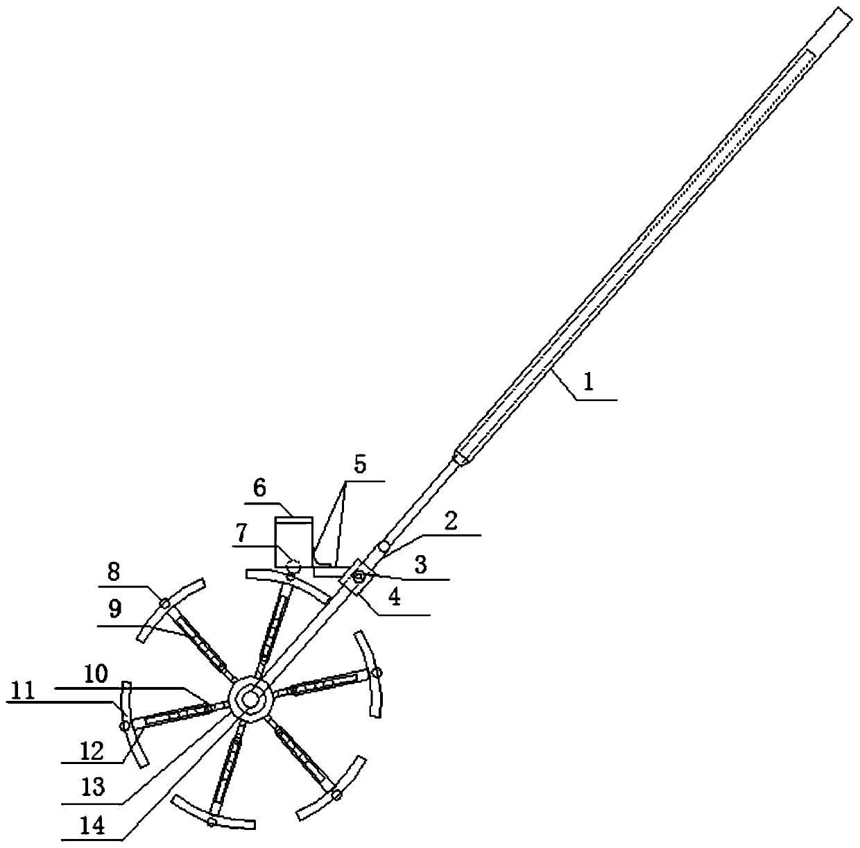
[0019] Such as figure 1 and figure 2 As shown, the adjustable reinforcing bar positioning device of the present invention has its main components as follows: 1-telescopic rod, 2-fork frame, 3-fixing bolt, 4-sliding sleeve, 5-fixed frame, 6-ink storage box, 7- - ink stick, 8-brush stick, 9-scale scale, 10-positioning lock nut, 11-brush table, 12-rotating telescopic rod, 13-rotating disc, 14-rotating bearing;

[0020] The telescopic rod 1 is telescopic, and the operator can adjust the length according to needs; the lower end of the telescopic rod 1 is connected with the fork frame 2 .

[0021] The fork frame 2 is a rod-shaped member connected in three sections, and the lower ends of the rods on both sides are perforated, and the rotating bearing 14 is fixed at the hole on the fork frame and is detachable.

[0022] There are two sliding sleeves 4, which are placed on the rods on both sides of the fork frame 2 and can slide up and down. The position of the sliding sleeve 4 on t...


PUM


Abstract

The invention relates to equipment for steel bar binding construction, in particular to an adjustable steel bar positioning and point distributing device. The adjustable steel bar positioning and point distributing device includes a telescopic rod, a fork, a fixing frame, an ink storage box, an ink-out stick, rotating telescopic rods, brushing tables and brushing sticks, wherein the fork is an n-shaped part fixed to the lower end of the telescopic rod, opening holes are formed in the lower ends of rods on both sides of the fork, rotating bearings penetrate into the holes, and rotating plates sleeve the rotating bearings; the two ends of the fixing frame are connected with sliding sleeves sleeving the rods on both sides of the fork; the ink storage box is fixed to the fixing frame, internally stores ink and is provided with a hole in the lower end; the upper end of the ink-out stick is inserted into the lower hole of the ink storage box, and one end of the ink-out stick is exposed; therotating telescopic rods are fixed to the rotating plates; the side surface of each brushing table is in an arc shape, and the brushing tables are annularly distributed and fixed to the rotating telescopic rods with the rotating bearings as the circle centers; the brushing sticks are fixed to the brushing tables, intermittently touch with the ink-out stick to stick ink and then paint points on theoperating surface along with rotation of the rotating plates; and the rebar spacing is ensured by adjusting the lengths of the telescopic rods, and the sliding sleeves are used for adjusting the position heights of the ink storage box to ensure that the brushing sticks are in contact with the ink-out stick. The adjustable steel bar positioning and point distributing device is suitable for a variety of different point distributing spacing requirements.

Description

technical field [0001] The invention relates to infrastructure engineering technology, in particular to equipment for binding steel bars. Background technique [0002] In the construction of reinforcement mesh binding in various fields, such as raft reinforcement reinforcement binding, independent foundation reinforcement reinforcement binding, structural slab reinforcement binding, reinforcement mesh binding and other constructions, it is particularly important to ensure the reinforcement spacing, mesh size and adjacent plate penetration of reinforcement mesh , the usual practice is that the operator sets the position of the steel bar by drawing a ruler at a certain distance, and uses a stone pen to describe it. This operation generally requires at least two people to cooperate with the operation, and the operation is inconvenient. It is time-consuming and laborious to repeat the same work many times, and manually mark the position The accuracy cannot be guaranteed, and dev...

Claims


Application Information

Patent Timeline
Patent Type & Authority Applications(China)
IPC IPC(8): E04C5/16
CPCE04C5/16
Inventor 李四喜林柏友
Owner 李四喜
Why Eureka
Try Eureka