Magnetic drive pump with pump shaft axial displacement monitoring device

A monitoring device and axial displacement technology, applied in pump device, pump control, measuring device and other directions, can solve the failure of the impeller and the pump cover seal ring, the observation of the axial movement of the pump shaft, and the axial fit of the rotor. and problems such as the increase in the amount of turbulence

Pending Publication Date: 2019-12-03
DANDONG TOP PUMP
View PDF0 Cites 0 Cited by
  • Summary
  • Abstract
  • Description
  • Claims
  • Application Information

AI Technical Summary

Problems solved by technology

After the friction pair surface of the thrust bearing and the sliding bearing is worn, the axial displacement of the magnetic pump shaft will increase, and the axial fit clearance and displacement of the rotor on the pump shaft will increase. The sealing rings between the pump bodies fail to cooperate, and even the magnetic rotor and the bearing seat have friction, which seriously affects the normal and safe operation of the pump.
However, the wear state of the pump shaft bearing device and the axial movement of the pump shaft cannot be observed from the outside of the pump, resulting in damage to the pump.

Method used


Image

  • Magnetic drive pump with pump shaft axial displacement monitoring device

Examples


Embodiment Construction

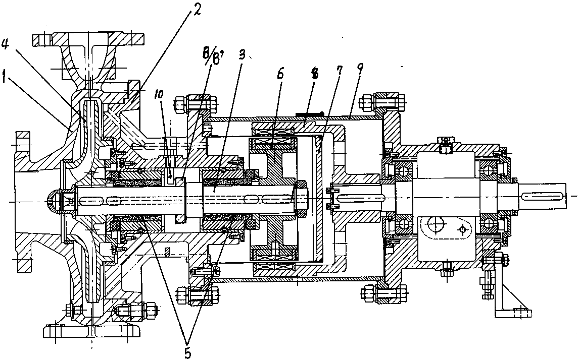
[0007] The magnetic pump of the present invention includes a pump body 1, a pump cover 2, a pump shaft 3, an impeller 4, a main shaft sliding bearing device 5, an inner magnetic rotor 6, an isolation sleeve 7, an outer magnetic rotor 8, and a sleeve bracket 9. An eddy current sensor probe 10 is installed on the pump cover 2, a collar B' is fixed on the shoulder of the pump shaft 3, and the head of the eddy current sensor probe 10 goes deep into the side of the collar B' The parts are arranged at a certain distance, and an eddy current sensor conversion device is arranged outside the magnetic pump body, and the eddy current sensor probe transmitter provided outside the pump body is connected with the eddy current sensor probe 10 signal wires.


PUM


Abstract

The invention discloses a magnetic drive pump with a pump shaft axial displacement monitoring device. The magnetic drive pump is characterized in that an eddy current sensor probe (10) is installed ona pump cover (2), and the head of the eddy current sensor probe (10) goes deep into the side portion of a shaft shoulder of the pump shaft (3) or goes deep into the side portion of a shaft sleeve component (B) fixedly connected to the pump shaft (3). The high-frequency oscillation current of the eddy current sensor probe generates an alternating magnetic field in a coil at the head of the probe to act with a metal surface close to the magnetic field, the single-value function of the distance delta is obtained from the characteristic impedance of the eddy current sensor, and the distance deltais converted into the change of the current through processing, so that the axial displacement of the pump shaft is monitored in real time, and when the axial displacement exceeds an allowable range,an alarm is given, and the pump is stopped for maintenance.

Description

technical field [0001] The invention relates to a magnetic pump, in particular to a magnetic pump with a pump shaft axial gap monitoring device. Background technique [0002] The silicon carbide thrust bearing of the magnetic pump and the end face of the sliding bearing form a pair of axial friction pairs, which bear unbalanced axial force. The magnetic pump seriously deviates from the working point, or the density and viscosity of the medium will affect the axial force of the pump. The magnitude and direction of . After the friction pair surface of the thrust bearing and the sliding bearing is worn, the axial displacement of the magnetic pump shaft will increase, and the axial fit clearance and displacement of the rotor on the pump shaft will increase. The sealing rings between the pump bodies fail to cooperate, and even the magnetic rotor and the bearing seat have friction, which seriously affects the normal and safe operation of the pump. However, the wear state of the ...

Claims


Application Information

Patent Timeline
IPC IPC(8): F04D15/02F04D13/06F04D13/02G01B7/02
CPCF04D15/0245F04D13/06F04D13/024G01B7/02
Inventor 孙月凤刘义昕贺传斌刘峰
Owner DANDONG TOP PUMP
Why Eureka
Try Eureka