
Robot positioning method and device

A robot positioning and pose technology, applied in the direction of navigation calculation tools, etc., can solve the problems of low robot precision and the inability of robots to complete tasks more accurately, and achieve the effect of improving positioning accuracy

Active Publication Date: 2019-12-03
ゼジャンハーレイテクノロジーカンパニーリミテッド
View PDF12 Cites 46 Cited by
  • Summary
  • Abstract
  • Description
  • Claims
  • Application Information

AI Technical Summary

Problems solved by technology

[0002] Existing technology can use mobile robots to perform tasks, such as handling goods in a warehouse, etc. The robot uses laser sensors to obtain laser point cloud data generated according to the current environment, creates a map of the current environment, and uses the laser point cloud data to position the robot , to determine the pose of the robot. When the environment where the mobile robot is located changes, such as when the original environment changes due to the handling of goods or staff walking, the laser point cloud data received by the laser sensor changes. At this time, it is not based on the current environment. The corresponding changes in the laser point cloud data are screened, and the robot is positioned directly using the received laser point cloud data, resulting in a low accuracy of the pose of the robot determined using the laser point cloud data, resulting in the robot being unable to complete the task more accurately.

Method used


Image

  • Robot positioning method and device
  • Robot positioning method and device
  • Robot positioning method and device

Examples


Embodiment 1

[0028] This embodiment proposes a robot positioning method. This embodiment mentions a plurality of special nouns, and the special nouns mentioned in this embodiment are explained as follows:

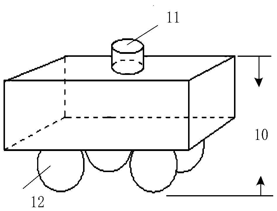
[0029] The "robot" in this embodiment is as figure 1 As shown, it includes a mobile base 10 and a laser sensor 11, wherein the mobile base 10 includes an odometer 12, a motion controller, a motor, a battery, and an embedded computer. The robot in this embodiment may be a robot capable of obtaining laser point cloud data and odometer information, and there is no excessive limitation on which components the robot specifically includes.

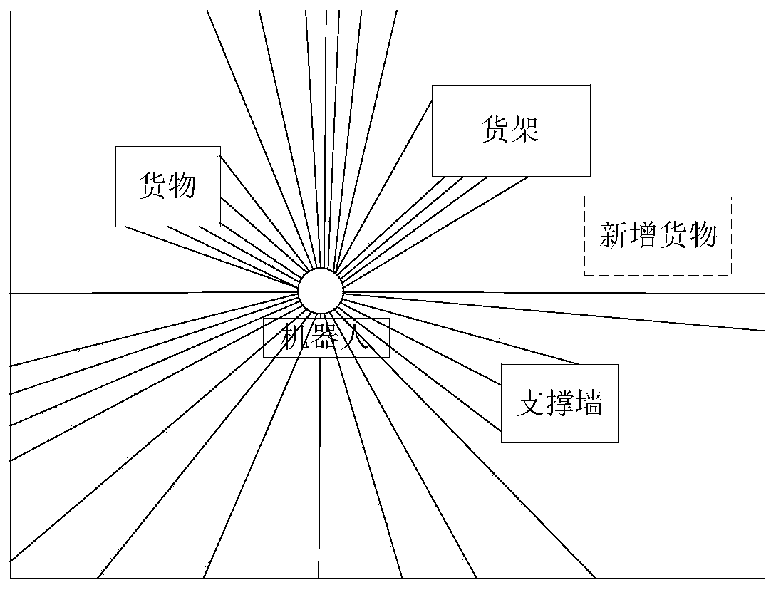
[0030] The "laser sensor 11" in this embodiment is a sensor used to obtain two-dimensional plane information, and is used to detect two-dimensional plane profile information of the surrounding environment. The scanning schematic diagram of the laser sensor is as follows figure 2 As shown, the laser sensor may be a 2D laser radar sensor, which is not lim...

Embodiment 2

[0117] This embodiment also provides a method for obtaining the pose from the laser point cloud data reflected by the reflector. The "reflector" in this embodiment is a material with strong laser reflectivity. When the laser data is scanned onto the reflector When , the point cloud received by the sensor has strong reflectivity and can be distinguished from the surrounding materials.

[0118] In this implementation, the laser point cloud data obtained at the initial moment can be traversed. When the reflectivity of the laser point cloud data is greater than the preset threshold, the laser point cloud data is used as the reflector data, indicating that the laser point cloud data is reflected from the reflector. Returned, you can judge the number of consecutive reflector data, the length of the reflector and the curvature of the current reflector, which are used to filter the interference points in the environment, such as filtering the environment and the reflector through the l...

Embodiment 3

[0162] This embodiment combines the above-mentioned implementations of Embodiment 1 and Embodiment 2. On the one hand, effective laser point cloud data and corresponding virtual point cloud data are used to perform pose correction. On the other hand, when the map update conditions are met, The current occupancy grid map can be updated. In the last aspect, the pose is obtained by using the laser point cloud data reflected from the reflector, and the latest determined pose is corrected.

[0163] Such as Figure 5 As shown, the specific implementation process is as follows:

[0164] Step 500: Obtain laser point cloud data at the initial moment, calibrate the position of the reflector, estimate the current pose based on the initial pose and odometer information, and generate an occupancy grid map at the same time;

[0165] Calibrate the position of the reflector: When determining the initial moment to obtain the laser point cloud data, determine the position of the robot in the w...


PUM


Abstract

The invention discloses a robot positioning method and device, and is used for removing point cloud data obtained by a laser sensor according to changes in the current environment of the robot, removing the impact of dynamic obstacles in the environment, and improving the accuracy of the map created and the positioning accuracy of the robot. The method comprises the following steps of acquiring laser point cloud data, and estimating the current pose in combination with odometer information; removing the newly added laser point cloud data from the laser point cloud data when determining that there are new laser point cloud data based on the acquired laser point cloud data and the currently occupied grid map to obtain effective laser point cloud data, wherein the newly added laser point cloud data are laser point cloud data generated by objects other than obstacles marked on the currently occupied grid map, and the occupied grid map is used to mark whether there is an obstacle at the grid position corresponding to the current environment; and correcting the current pose based on the currently occupied grid map by using the effective laser point cloud data.

Description

technical field [0001] The invention relates to the field of positioning technology, in particular to a robot positioning method and equipment. Background technique [0002] Existing technology can use mobile robots to perform tasks, such as handling goods in a warehouse, etc. The robot uses laser sensors to obtain laser point cloud data generated according to the current environment, creates a map of the current environment, and uses the laser point cloud data to position the robot , to determine the pose of the robot. When the environment where the mobile robot is located changes, such as when the original environment changes due to the handling of goods or staff walking, the laser point cloud data received by the laser sensor changes. At this time, it is not based on the current environment. The corresponding changes in the laser point cloud data are screened, and the robot is positioned directly using the received laser point cloud data, resulting in a low accuracy of th...

Claims


Application Information

Patent Timeline
IPC IPC(8): G01C21/20
CPCG01C21/20
Inventor 胡立志林辉卢维殷俊穆方波
Owner ゼジャンハーレイテクノロジーカンパニーリミテッド
Features
  • Generate Ideas
  • Intellectual Property
  • Life Sciences
  • Materials
  • Tech Scout
  • Unparalleled Data Quality
  • Higher Quality Content
  • 60% Fewer Hallucinations
Learn More