Wideband radar aperture transit effect adaptive compensation method

An adaptive compensation and aperture transition technology, applied in the field of radar array transmission and reception, can solve problems such as difficult sub-array phase center relationship, deviation in delay difference compensation, deviation in compensation delay difference calculation, etc., to achieve enhanced detection performance , Improve the effect of compensation accuracy

Active Publication Date: 2019-12-03
BEIJING INSTITUTE OF TECHNOLOGYGY
View PDF20 Cites 8 Cited by
  • Summary
  • Abstract
  • Description
  • Claims
  • Application Information

AI Technical Summary

Problems solved by technology

[0005] The compensation methods mentioned above are becoming more and more refined and simpler from analog to digital, but these methods have a common disadvantage. The compensation delay is assumed to be known in the phase center of the subarray, and the geometric method is used according to the beam pointing. Obviously, the calculated results cannot meet the needs of practical applications.
There are three reasons. First, the relationship between the subarray phase centers is unknown. With the development of technology, the subarray structure has developed from a planar array to a conformal array. In addition, the subarray division techniques proposed for various optimization indicators have become increasingly abundant, including Non-uniform division, overlapping division, etc., it is difficult to determine the phase center relationship of each sub-array, so the geometric calculation method is difficult; second, there is an error in the calculation of the aperture transit time, and the existing methods calculate the aperture transit time according to the beam pointing angle, but The target position is within the range of the main lobe, but not necessarily at the normal position of the beam, resulting in a deviation in the calculation of the compensation delay difference; third, the cable length between channels is sensitive to temperature, and the delay difference between channels will change with the Changes in the ambient temperature and device response, etc., blindly compensate according to the value calibrated when the system leaves the factory, resulting in deviations in the compensation of the delay difference
[0006] In summary, there is currently a lack of an aperture transition effect compensation method that can be applied to broadband phased array radars with any antenna configuration and any sub-array division.

Method used


Image

  • Wideband radar aperture transit effect adaptive compensation method
  • Wideband radar aperture transit effect adaptive compensation method
  • Wideband radar aperture transit effect adaptive compensation method

Examples


Embodiment Construction

[0041] The present invention will be described in detail below with reference to the accompanying drawings and examples.

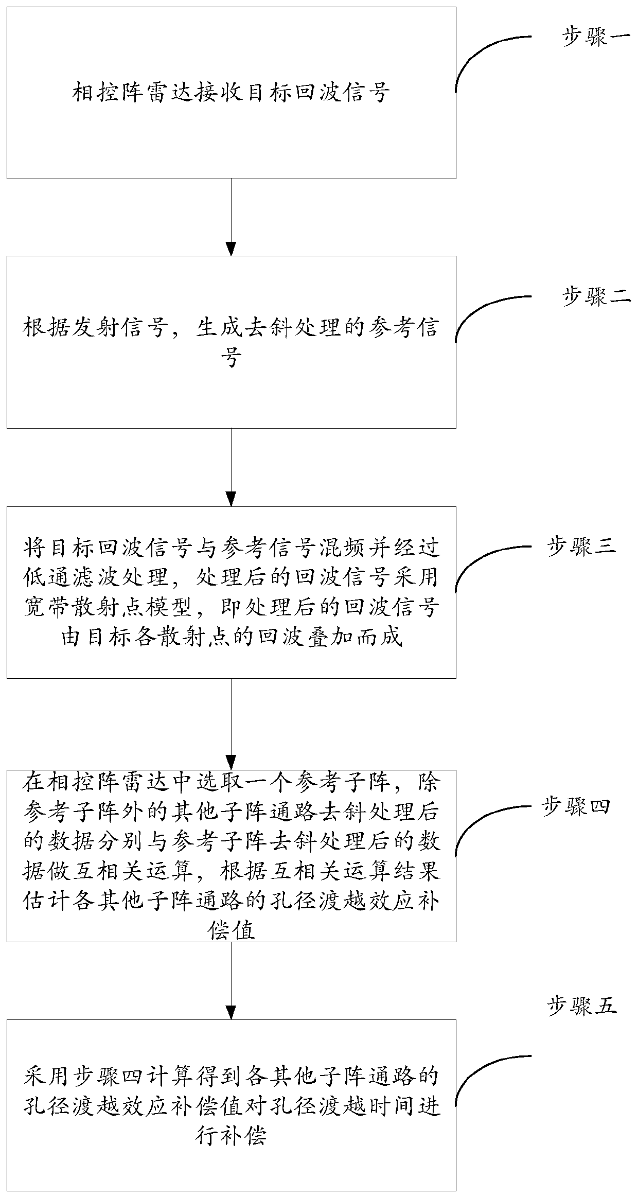
[0042] The present invention provides a method for self-adaptive compensation of Chirp signal aperture transition effect based on cross-correlation, the process is as follows figure 1 As shown, the method uses the linear frequency modulation signal Chirp signal as the transmitting signal, and specifically includes the following steps:

[0043] Step 1: The phased array radar receives target echo signals.

[0044] The standard echo signal in the embodiment of the present invention is s r (t);

[0045]

[0046] Among them, T p Chirp signal pulse width, f 0 It is the starting frequency of Chirp signal, k=B / T p is the FM slope of the Chirp signal, B is the signal bandwidth, and t is the time axis.

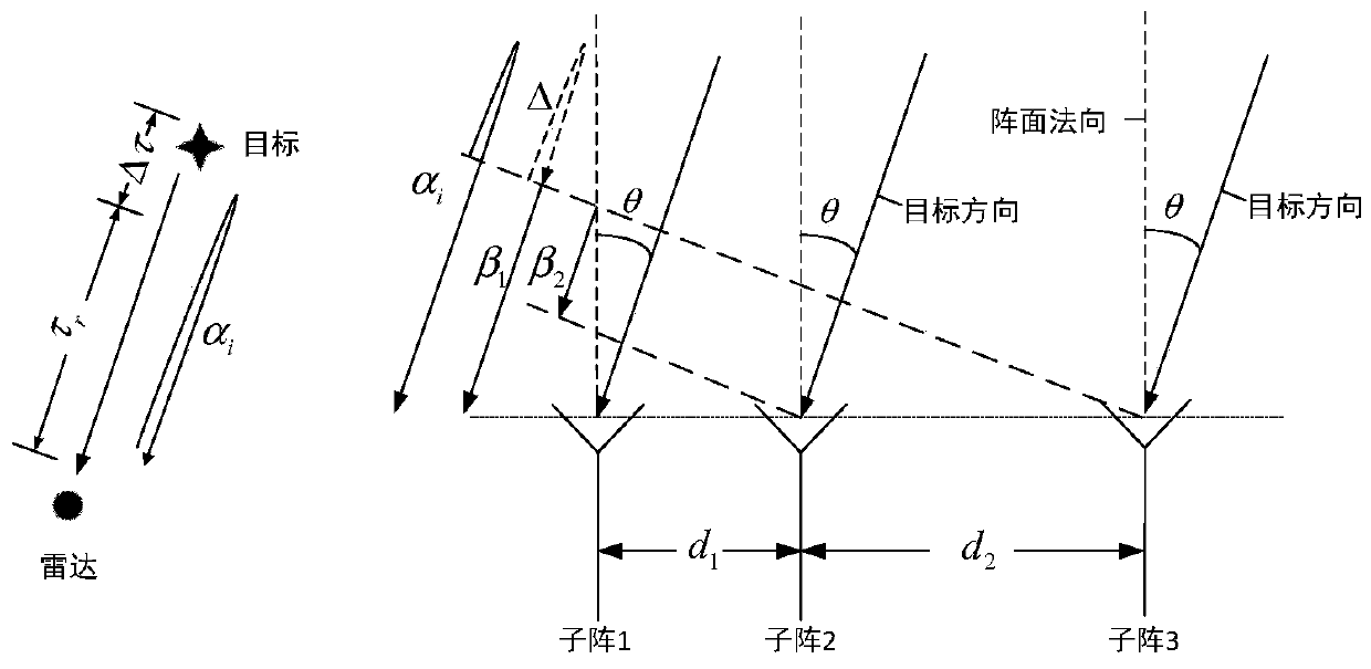
[0047] The schematic diagram of the phased array radar array is as follows: figure 1 As shown, the array structure can be a planar array or a conformal ar...


PUM


Abstract

The invention discloses a wideband radar aperture transit effect adaptive compensation method. By means of the method, the aperture transit time difference can be adaptively compensated. The method takes a Chirp signal as a transmitting signal, and specifically comprises the following steps of receiving a target echo signal by a phased array radar; according to the transmitting signal, generatinga dechirped reference signal; performing frequency mixing and low-pass filtering on the target echo signal and the reference signal, wherein the processed echo signal adopts a wideband scattering point model, namely, the processed echo signal is formed by superposing echoes of target scattering points; selecting a reference subarray in the phased array radar, performing cross correlation operationon dechirped data of paths of other subarrays except the reference subarray and dechirped data of the reference subarray, and estimating the aperture transit effect compensation values of the paths of other subarrays according to a cross correlation operation result; and compensating the aperture transit time by adopting the calculated aperture transit effect compensation values of the paths of other subarrays.

Description

technical field [0001] The invention relates to the technical field of radar array transmission and reception, in particular to an adaptive compensation method for broadband radar aperture transition effect. Background technique [0002] In order to obtain high range resolution, the radar needs to use a large-bandwidth transmission signal, and a wide-band linear frequency modulation signal (LFM, Chirp) is a good choice; in order to obtain high angular resolution, the typical method is to increase the radar aperture, but large There is an inherent contradiction between the signal bandwidth of the aperture phased array radar and the electronic scanning capability of the beam, and this contradiction is manifested as the aperture transition effect. Wide-angle wide-angle scanning of large-aperture broadband radar will cause beam pointing deviation, resulting in energy loss of the synthesized echo signal, broadening of the main lobe after pulse pressure, and reduction of distance ...

Claims


Application Information

Patent Timeline
Patent Type & Authority Applications(China)
IPC IPC(8): G01S7/41
CPCG01S7/41
Inventor 龙腾梁振楠刘泉华毛二可
Owner BEIJING INSTITUTE OF TECHNOLOGYGY
Why Eureka
Try Eureka