Device and method for improving antenna gain of mobile phone mobile terminal to realize long-distance reading of high-frequency tag

A mobile phone mobile terminal, high-frequency tag technology, applied in computer parts, instruments, induction record carriers, etc., can solve the problem of high-frequency tags being unavailable, reducing the application scenarios of high-frequency tags, etc.

Pending Publication Date: 2019-12-03
ARIZON RFID TECH YANGZHOU
View PDF3 Cites 0 Cited by
  • Summary
  • Abstract
  • Description
  • Claims
  • Application Information

AI Technical Summary

Problems solved by technology

[0002] Conventional radio frequency tags include high-frequency tags and ultra-high-frequency tags. UHF tags are long-distance tags, and the reading distance is generally about 10M. High-frequency tags are short-range tags. The distance between industrial readers is < The distance of 10cm, but the reading of high-frequency tags is related to the size of the antenna. When using mobile devices such as the NFC function of mobile phones to read, the maximum reading distance of high-frequency tags is <3cm; so the conventional reading distance of high-frequency tags is < With a distance range of 10cm, the reading distance of high-frequency tags using the NFC function is reduced to <3cm, which greatly reduces the application scenarios of high-frequency tags; for example, the method of reading high-frequency tags by conventional mobile terminals is: tag After attaching to the surface of the product, use a mobile phone or mobile terminal to get close to the radio frequency tag to read the distance. When the tag needs to be attached to the product package, when the mobile terminal is more than 3cm from the mobile terminal to the label in the package, the high frequency tag will not be able to use

Method used


Image

  • Device and method for improving antenna gain of mobile phone mobile terminal to realize long-distance reading of high-frequency tag

Examples


Embodiment Construction

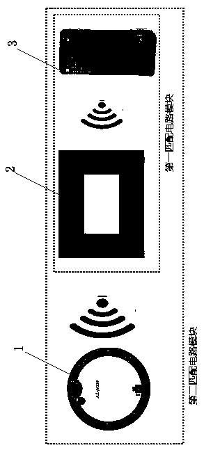
[0014] The present invention will be described in detail below in conjunction with the accompanying drawings.

[0015] A device for improving the antenna gain of a mobile phone mobile terminal to realize long-distance reading of high-frequency tags, structurally comprising a wireless high-frequency RFID tag 1, a mobile phone mobile terminal antenna 3; An amplified antenna 2 is placed between them; the amplified antenna 2 is composed of a coil winding, the amplified antenna 2 and the mobile terminal antenna 3 are matched to form the first matching circuit module, and the wireless high-frequency RFID tag 1 is matched with the first matching circuit module to form the second matching circuit module. Matching circuit module; the amplifying antenna 2 utilizes coil winding to perform coupling induction with the mobile terminal antenna 3 to increase the gain of the mobile terminal antenna 3, thereby achieving the purpose of signal amplification and making the signal of the mobile term...


PUM

PropertyMeasurementUnit
Sizeaaaaaaaaaa

Abstract

The invention relates to a device and a method for improving antenna gain of a mobile phone mobile terminal to realize long-distance reading of a high-frequency tag. The device comprises a wireless high-frequency RFID tag, an amplification antenna and a mobile phone mobile terminal antenna. The amplification antenna is formed by winding a coil. The amplification antenna and a mobile phone mobile terminal antenna are matched to form a first matching circuit module, and the wireless high-frequency RFID tag and the first matching circuit module are matched to form a second matching circuit module; the amplification antenna increases the gain of the mobile phone mobile terminal antenna in a mode of coupling induction with the mobile phone mobile terminal antenna in a coil winding mode, therebyachieving the purpose of signal amplification, enabling the mobile phone mobile terminal antenna to be stronger in signal, and achieving the long-distance reading of a wireless high-frequency RFID tag. According to the invention, the amplification antenna increases the gain of the mobile phone antenna in a mode of coupling induction with the mobile phone mobile terminal antenna in a coil windingmode, thereby achieving the purpose of signal amplification, enabling a mobile phone mobile terminal signal to be stronger, and enabling a long-distance label to be read.

Description

technical field [0001] The invention relates to a device and method for increasing the antenna gain of a mobile terminal to realize long-distance reading of high-frequency tags, and belongs to the technical field of high-frequency tag reading design. Background technique [0002] Conventional radio frequency tags include high-frequency tags and ultra-high-frequency tags. UHF tags are long-distance tags, and the reading distance is generally about 10M. High-frequency tags are short-range tags. The distance between industrial readers is < The distance of 10cm, but the reading of high-frequency tags is related to the size of the antenna. When using mobile devices such as the NFC function of mobile phones to read, the maximum reading distance of high-frequency tags is <3cm; so the conventional reading distance of high-frequency tags is < With a distance range of 10cm, the reading distance of high-frequency tags using the NFC function is reduced to <3cm, which greatly...

Claims


Application Information

Patent Timeline
IPC IPC(8): G06K7/10
CPCG06K7/10346G06K7/10356
Inventor 范琳琳
Owner ARIZON RFID TECH YANGZHOU
Why Eureka
Try Eureka