Intelligent traffic signal indication device

A technology for traffic signals and indicating devices, applied in the field of intelligent traffic signal indicating devices, can solve the problems of stable placement of signal lights, inconvenient adjustment and use, inability to adjust the height of signal lights, etc., and achieves the effect of enhancing structural stability

Inactive Publication Date: 2019-12-03
兰杰
View PDF6 Cites 3 Cited by
  • Summary
  • Abstract
  • Description
  • Claims
  • Application Information

AI Technical Summary

Problems solved by technology

[0005] Aiming at the deficiencies of the prior art, the present invention provides an intelligent traffic signal indicating device, which has the advantages of avoiding the problem that the mobility of the universal wheel affects the stable placement of the signal lamp body, and can realize the adjustment of the height of the signal lamp body, which solves the problem of existing The emergency signal lights in the technology are moved by the universal wheels added at the bottom, but when the signal lights are placed stably, the mobility of the universal wheels will easily affect the stable placement of the signal lights, even the universal wheels with self-locking devices can not Due to the small contact area between the universal wheel and the ground, the frictional resistance is small so that the signal light cannot be placed stably, and the height of the signal light cannot be adjusted, which is very inconvenient when it needs to be adjusted. When the signal light is hit, the impact force will directly act on it On the signal lamp, it is easy to cause damage to the signal lamp and affect the use of the problem

Method used


Image

  • Intelligent traffic signal indication device
  • Intelligent traffic signal indication device
  • Intelligent traffic signal indication device

Examples


Embodiment Construction

[0026] The technical solutions in the embodiments of the present invention will be clearly and completely described below. Obviously, the described embodiments are only some of the embodiments of the present invention, but not all of them. Based on the embodiments of the present invention, all other embodiments obtained by persons of ordinary skill in the art without making creative efforts belong to the protection scope of the present invention.

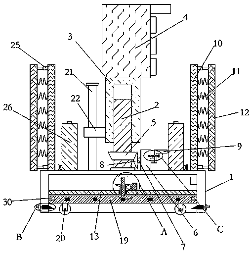
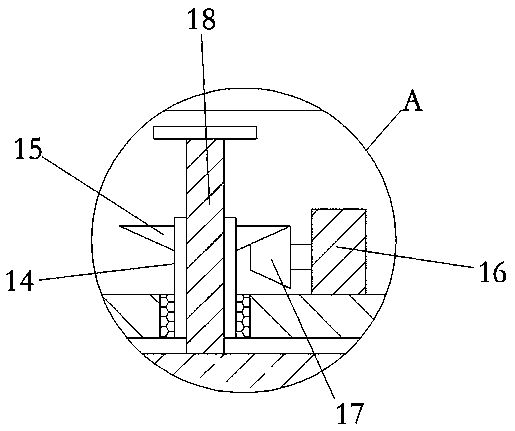
[0027] see Figure 1-4 , an intelligent traffic signal indicating device, comprising a base 1, the center of the upper end of the base 1 is rotatably connected with a rotating screw 2, the outer wall of the upper end of the rotating screw 2 is threadedly connected with a lifting screw 3, and the upper end of the lifting screw 3 is fixedly connected with a signal light The body 4, the outer wall of the lower end of the rotating screw 2 is fixedly sleeved with the first driven helical gear 5, the upper end of the base 1 is fixedly con...


PUM


Abstract

The invention relates to the technical field of the traffic equipment, and discloses an intelligent traffic signal indication device. The device comprises a base, a rotating screw is rotatably connected to the center of an upper end of the base, a lifting screw tube is connected to the outer wall of the upper end of the rotating screw in a threaded manner, and the upper end of the lifting screw tube is fixedly connected with a signal lamp body; a first driven bevel gear is fixedly sleeved on the outer wall of a lower end of the rotating screw, the upper end of the base is fixedly connected with a bearing seat, a rotating rod is connected into the bearing seat in a rotating manner through a ball bearing; one end of the rotating rod is fixedly connected with a first driving bevel gear engaged with the first driven bevel gear, and the other end of the rotating rod is fixedly connected with an L-shaped handle; the upper end of the base is further symmetrically and fixedly connected with two fixed plates; back sides of two fixed plates are fixedly connected with the same buffer plate through multiple buffer springs. The intelligent traffic signal indication device disclosed by the invention can avoid the problem that the stable placing of the signal lamp body is influenced due to the mobility of the universal wheel, and the advantage of regulating the height of the signal lamp bodycan be realized.

Description

technical field [0001] The invention relates to the technical field of traffic equipment, in particular to an intelligent traffic signal indicating device. Background technique [0002] A traffic signal light is a signal light for directing traffic operation, and generally consists of a red light, a green light, and a yellow light. Red light means prohibition of passage, green light means permission to pass, yellow light means warning, traffic signal lights are divided into: motor vehicle signal lights, non-motor vehicle signal lights, crosswalk signal lights, direction indicator lights (arrow signal lights), lane signal lights, flashing warning lights, road Signal lights at level crossings with railways. [0003] When the main signal light at the intersection is damaged, it is necessary to use the emergency signal light to assist the smooth running of the road. The current emergency signal light is moved by the universal wheel added at the bottom, but when the signal light...

Claims


Application Information

Patent Timeline
Patent Type & Authority Applications(China)
IPC IPC(8): G08G1/0955
CPCG08G1/0955
Inventor 兰杰
Owner 兰杰
Why Eureka
Try Eureka