Liquid-cooled motor shell and manufacturing method thereof

A motor casing and liquid cooling technology, which is applied in the manufacture of motor generators, casings/covers/supports, electrical components, etc., can solve problems such as safety accidents, inner wall thickness of the casing, and easy leakage of liquid, so as to improve production efficiency , reduced wall thickness, easy to install and fix

Pending Publication Date: 2019-12-03
重庆新铝时代科技股份有限公司
View PDF0 Cites 0 Cited by
  • Summary
  • Abstract
  • Description
  • Claims
  • Application Information

AI Technical Summary

Problems solved by technology

[0017] The invention provides a structural design of a screw hole on the end surface of a liquid-cooled motor casing to solve the technical proble

Method used


Image

  • Liquid-cooled motor shell and manufacturing method thereof
  • Liquid-cooled motor shell and manufacturing method thereof
  • Liquid-cooled motor shell and manufacturing method thereof

Examples


Embodiment 1

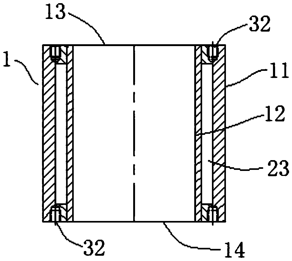
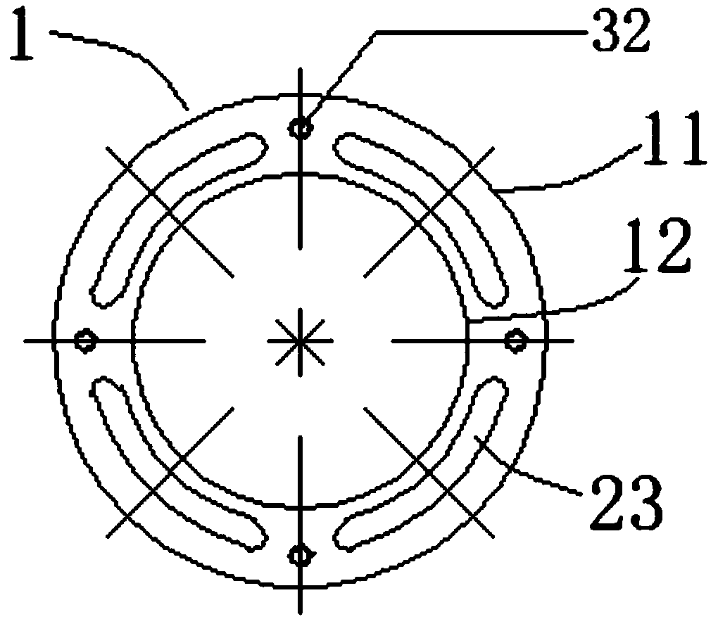
[0093] Such as figure 1 , figure 2 As shown, in the prior art, the threaded holes 32 of the upper end face 13 and the lower end face 14 of the motor casing are usually on the corresponding two ends of the casing wall. In order to ensure the overall strength of the motor after assembly, the size of the threaded holes 32 will be There are corresponding design requirements. When designing the wall thickness of the corresponding shell 1, it is necessary to consider adding a certain thickness on both sides of the threaded hole 32 to ensure the strength of the hole. In particular, there is a U-shaped coolant channel 23 inside the wall of the liquid-cooled casing. The two ends of the casing are welded and sealed by sealing blocks. Adding threaded holes 32 on both ends will increase the difficulty of welding, affect the sealing of the welding and cause coolant leakage, especially to the inside of the motor. The coolant and the motor Contact with internal parts can easily cause safet...

Embodiment 2

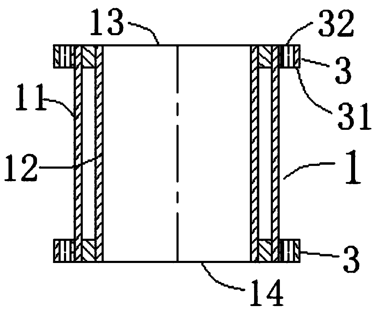
[0100] Such as Figure 3-Figure 8As shown, in another preferred embodiment mentioned in the present invention, a liquid-cooled motor casing includes not only all the technical features mentioned in Embodiment 1, but also a sealing structure for the cooling liquid channel 23 . The sealing structure includes a continuous U-shaped cooling liquid channel 23 arranged in the housing 1, and the two ends of the housing are located on the inner side of the continuous U-shaped cooling liquid channel 23. Annular blocking protrusions 24 are arranged, and the blocking protrusions 24 are connected with the housing. 1 is coaxial, and the two blocking protrusions 24 are integrally formed with the housing 1; the two ends of the housing 1 are located outside the blocking protrusions 24, and an annular sealing block 25 that can seal the continuous U-shaped coolant passage 23 is provided ; Between the sealing block 25 and the blocking protrusion 24, between the sealing block 25 and the housing 1 ...

Embodiment 3

[0103] Such as Figure 3-4 , Figure 9-11 As shown, in another preferred embodiment of the present invention, as an improvement of Embodiment 2, the lug 31 is installed on the outside of the sealing block 25, and the lug 31 can be installed on the sealing block by welding or casting. 25 on.


PUM


Abstract

The invention discloses a liquid-cooled motor shell. The liquid-cooled motor shell comprises a shell body, an upper end face, a lower end face, a water inlet and a water outlet, the shell body comprises an outer wall and an inner wall, and the liquid-cooled motor shell is characterized by further comprising a hanging lug with a screw hole, the hanging lug is arranged in the outer wall area of theupper end face and/or the lower end face, and the screw hole is formed in the hanging lug. As a preferred scheme, a fastening ring is also arranged on the motor shell and is used for installing and arranging a hanging lug. According to the structural design that the screw holes are formed in the outer wall of the end face of the liquid-cooled motor shell, the technical problems that in an existingsealing structure, the inner wall of the shell is thick, liquid leakage is likely to happen, and safety accidents are caused are solved. The strength of the screw holes is ensured, the motor shell and the end cover are convenient to install and fix, and the shell is lighter by reducing the wall thickness of the shell; and moreover, the end face welding sealing process is optimized, so that the welding operation is simpler and more convenient, and the welding sealing performance is better. Particularly, the motor shell provided with the fastening ring increases the fastening strength of the motor shell and improves the safety and stability of equipment.

Description

technical field [0001] The invention relates to the field of motors, in particular to a liquid-cooled motor casing and a manufacturing method. Background technique [0002] As a commonly used device, the motor is widely used in production and life. The motor is an electromagnetic device that realizes the conversion or transmission of electric energy according to the law of electromagnetic induction. Its main function is to provide power for various electrical appliances or machinery. For example, in the field of electric vehicles, the motor can generate driving torque as the power source for the advancement of electric vehicles. . During the operation of the motor, a lot of heat will be generated. If the heat is not transferred away in time, the temperature of the motor will increase, and finally the life of the motor will be shortened, and even directly cause the motor to be overheated during operation. And burned. At present, in order to better dissipate heat from the m...

Claims


Application Information

Patent Timeline
IPC IPC(8): H02K5/20H02K9/193H02K15/14
CPCH02K5/20H02K9/193H02K15/14
Inventor 尹兴满
Owner 重庆新铝时代科技股份有限公司
Why Eureka
Try Eureka