Artificial-intelligence-based feed putting device

A feeding device and artificial intelligence technology, applied in the field of artificial intelligence, can solve the problems of affecting the feeding effect, uneven feeding, high labor intensity, etc., and achieve the effect of improving the moving effect, ensuring the quality of the feed, and reducing the labor intensity

Active Publication Date: 2019-12-06
XUZHOU BODAO TECH PROMOTION SERVICE
View PDF9 Cites 6 Cited by
  • Summary
  • Abstract
  • Description
  • Claims
  • Application Information

AI Technical Summary

Problems solved by technology

[0003] Feeding in the existing feed field is still dominated by manpower. This operation method is labor-intensive, and the feeding is not uniform enough, which affects the feeding effect. Therefore, it is necessary to design an artificial intelligence-based feeding device that can feed regularly and uniformly.

Method used


Image

  • Artificial-intelligence-based feed putting device
  • Artificial-intelligence-based feed putting device
  • Artificial-intelligence-based feed putting device

Examples


Embodiment 1

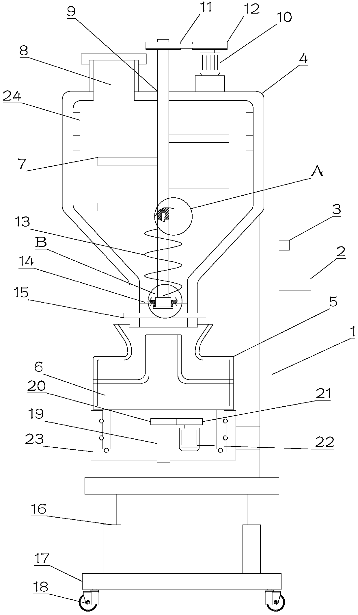
[0023] see figure 1 , in Embodiment 1 of the present invention, an artificial intelligence-based feeding device includes a bracket 1, and the bracket 1 is sequentially provided with a material storage box 4 and a material distribution box 5 from top to bottom, and the first rotating shaft 9 runs through the material storage box 4. The top is provided with a driving mechanism on the top of the first rotating shaft 9, and a stirring rod 7 is fixedly installed on the first rotating shaft 9. A feeding auger 13 is installed at the bottom of the first rotating shaft 9. A discharge port is arranged at the bottom of the material box 4, and the conveying auger 13 is arranged inside the discharge port, and an on-off valve 15 is arranged on the discharge port, and the on-off valve 15 is set to control the switch of the discharge port.

[0024] The storage box 4 is also provided with a feeding port 8, which is convenient for adding materials to the storage box 4. The inside of the storage...

Embodiment 2

[0030] see Figure 1~4 The main difference between this embodiment 2 and embodiment 1 is that the drive mechanism includes an A pulley 11 installed on the first rotating shaft 9, and the A pulley 11 is connected to the B pulley on the output end of the first motor 10 through a belt. 12 on.

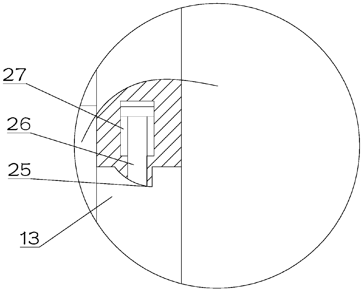
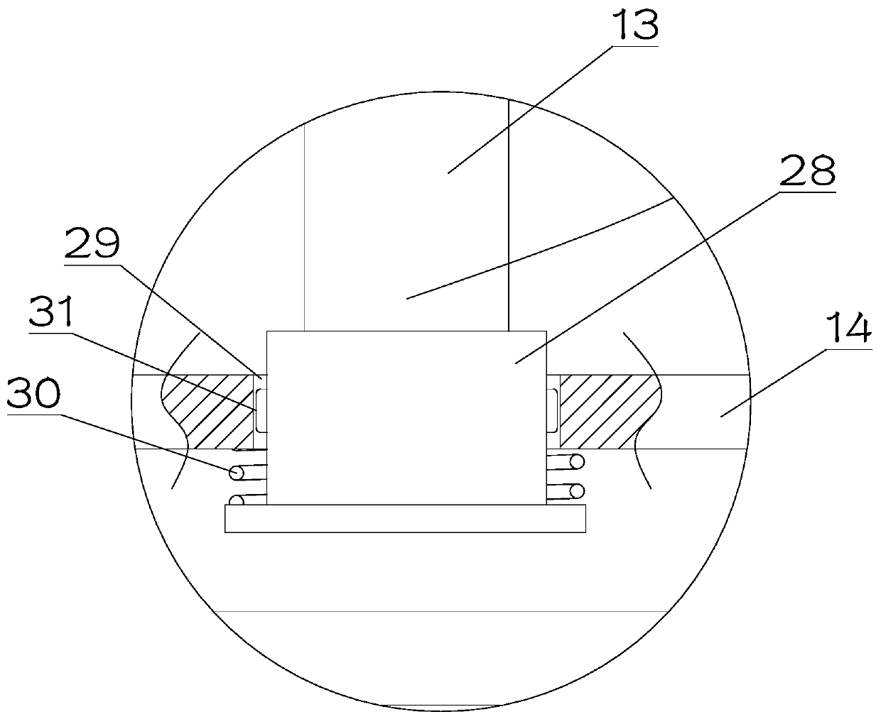
[0031] The top of the feeding auger 13 is provided with a groove 25 cooperating with the bump on the first rotating shaft 9, the right side of the groove 25 is vertically arranged, and the left side is arc-shaped; the top of the feeding auger 13 is The center position is provided with a slide bar 26, the upper end of the slide bar 26 is provided with a slide block, the slide block is set in the chute 27 on the first rotating shaft 9, and the bottom of the feeding auger 13 is rotated and set on the second In the rotating shaft 28, the two sides of the second rotating shaft 28 are provided with sliders 31 installed on the chute 29, the sliding blocks 31 are arranged on the support rod 14, a...


PUM


Abstract

The invention discloses an artificial-intelligence-based feed putting device, and relates to the technical field of artificial intelligence. The artificial-intelligence-based feed putting device comprises a support, the support is provided with a storage box and a scattering box from top to bottom in sequence, a first rotary shaft penetrates through the top of the storage box, a driving mechanismis arranged at the top of the first rotary shaft, stirring rods are further fixed to the first rotary shaft, and a conveying auger is installed at the bottom of the first rotary shaft; a discharging port is formed in the bottom of the storage box, the conveying auger is arranged inside the discharging port, an opening-closing valve is arranged in the discharging port, and a rotary mechanism is arranged on the scattering box; the scattering box comprises a conveying box A and a conveying box B arranged at the bottom of the conveying box A, a feed inlet of the conveying box A is formed in the outer side of the conveying box B, and the side faces of the conveying box A and the conveying box B are both provided with a feed outlet. By means of the artificial-intelligence-based feed putting device, materials are prevented from being hardened, the feed putting area is increased, energy is saved, and movement is facilitated; timing feed putting is achieved, the intelligentization is improved,and the labor intensity is reduced.

Description

technical field [0001] The invention relates to the technical field of artificial intelligence, in particular to an artificial intelligence-based feeding device. Background technique [0002] Artificial intelligence is a new technical science that studies and develops theories, methods, technologies and application systems for simulating, extending and expanding human intelligence. Artificial intelligence is a branch of computer science that attempts to understand the essence of intelligence and produce a new intelligent machine that can respond in a manner similar to human intelligence. Research in this field includes robotics, language recognition, image recognition, natural language processing and expert systems, etc. Since the birth of artificial intelligence, the theory and technology have become increasingly mature, and the application fields have also continued to expand. It can be imagined that the technological products brought by artificial intelligence in the fut...

Claims


Application Information

Patent Timeline
Patent Type & Authority Applications(China)
IPC IPC(8): A01K5/02A01K5/00A01K39/012A01K61/80A23L5/20A23L5/30
CPCA01K5/004A01K5/0291A01K39/0125A23L5/20A23L5/30A01K61/80Y02A40/81
Inventor 李珂张雪晴
Owner XUZHOU BODAO TECH PROMOTION SERVICE
Why Eureka
Try Eureka