Multi-shaft drive bending machine and bending method thereof

A multi-axis drive, bending machine technology, applied in the direction of forming tools, feeding devices, positioning devices, etc., can solve the problem that the bending angle cannot be achieved, the bending shape and bending angle are limited, and the work efficiency is reduced. problems, to achieve a reasonable and reliable overall structure, reduce the difficulty of bending, and improve work efficiency

Pending Publication Date: 2019-12-06
南京蓝昊智能科技有限公司
View PDF0 Cites 20 Cited by
  • Summary
  • Abstract
  • Description
  • Claims
  • Application Information

AI Technical Summary

Problems solved by technology

[0002] The bending machine in the prior art completes the bending through the linkage of the upper and lower bending knives, but the existing bending machines generally have relatively significant shortcomings: the shape and bending angle formed by the bending machine are limited, and it is not easy to control, can not achieve any required shape and required bending angle; this is mainly reflected in two points, one is the problem of the driving mode, the existing bending machine drive can not realize the multi-axis simultaneous linkage mechanism, so that the bending knife The head can reach any position, which leads to the limitation of its bending shape and bending ang

Method used


Image

  • Multi-shaft drive bending machine and bending method thereof
  • Multi-shaft drive bending machine and bending method thereof
  • Multi-shaft drive bending machine and bending method thereof

Examples


Embodiment Construction

[0046] The present invention will be further illustrated below in conjunction with the accompanying drawings and specific embodiments. This embodiment is implemented on the premise of the technical solution of the present invention. It should be understood that these embodiments are only used to illustrate the present invention and are not intended to limit the scope of the present invention.

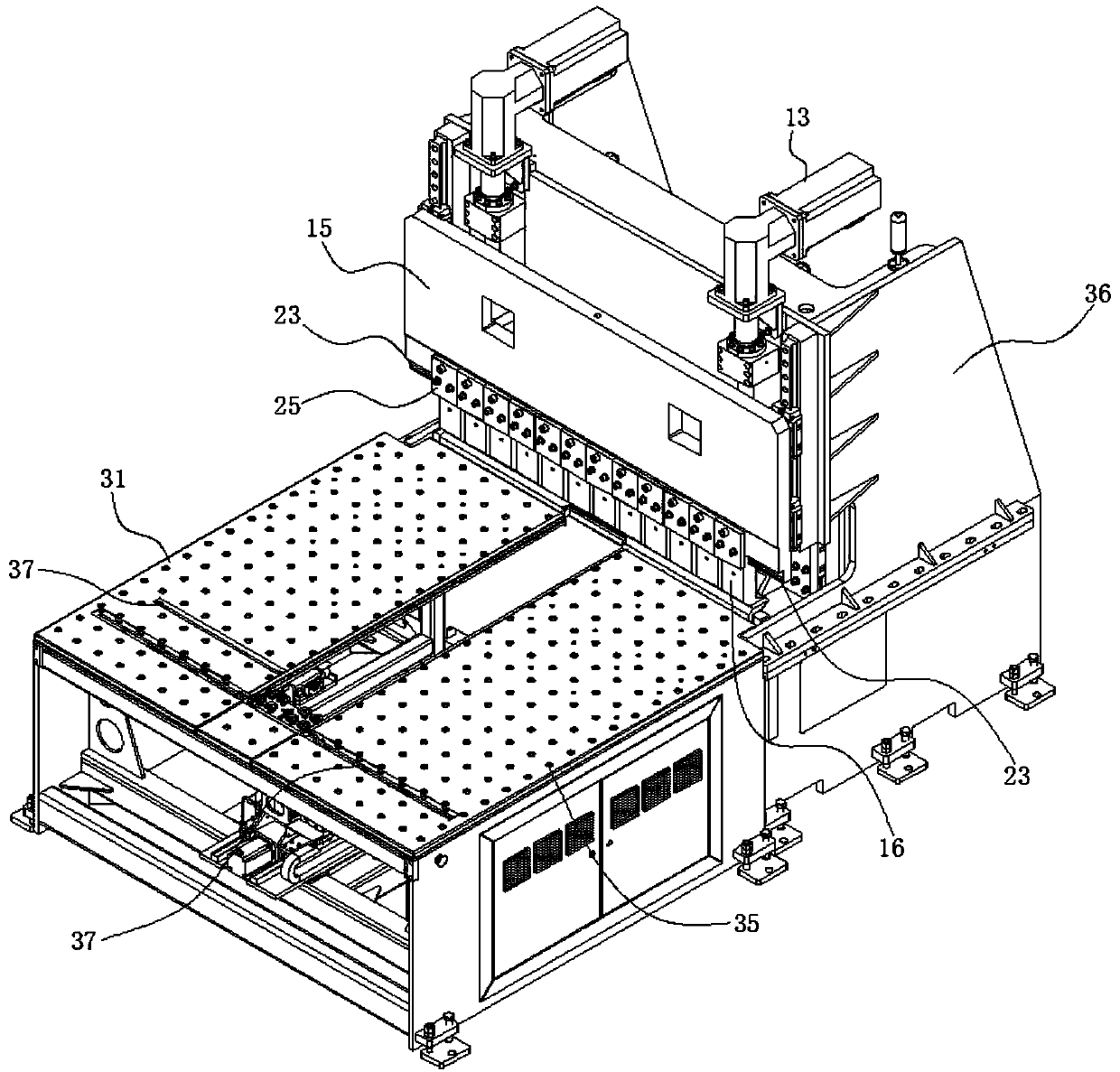
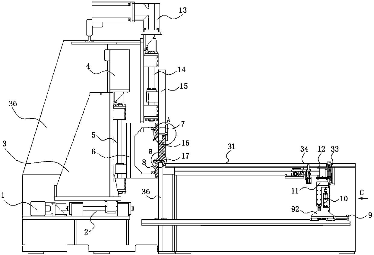
[0047] Such as figure 1 and figure 2 As shown, as shown, a multi-axis drive bending machine includes a bending system and an integrated loading and unloading system; the bending system includes a horizontal bending drive device 1, and the horizontal bending drive device 1 is equipped with a horizontal The horizontal bending shaft 2 set in the direction; the horizontal bending shaft 2 is equipped with a linkage bracket 3; The upper and lower bending shafts 5 in the vertical direction are installed, and the shaft ends of the described bending shafts 5 are equipped with bending knife bra...


PUM


Abstract

The invention discloses a multi-shaft drive bending machine which comprises a bending system and an integrated feeding and discharging system. The bending system comprises a horizontal bending drive device. A horizontal bending shaft arranged in the horizontal direction is installed on the horizontal bending drive device. A linkage support is installed on the horizontal bending shaft. An up and down bending drive device is further arranged at the upper end of the linkage support. An up and down bending shaft installed in the vertical direction is installed on the up and down bending drive device. A bending cutter support is installed at the shaft end of the up and down bending shaft. An upper bending cutter and a lower bending cutter are installed at the upper end and the lower end of thebending cutter support correspondingly, wherein the upper bending cutter and the lower bending cutter correspond in upper and lower position. According to the multi-shaft drive bending machine, by means of coordinative matching and adjusting of bending drive, the upper bending cutter and the lower bending cutter can reach different positions, a down pressing drive lifting device cooperates to control down pressing fixing and loosening of an upper pressing cutter and feeding and discharging action of feeding and discharging drive, and bending of bent parts in any shape, at any angle and with any flexible radian is completed.

Description

technical field [0001] The invention relates to the field of bending equipment and bending devices, in particular to a multi-axis drive bending machine and a bending method thereof. Background technique [0002] The bending machine in the prior art completes the bending through the linkage of the upper and lower bending knives, but the existing bending machines generally have relatively significant shortcomings: the shape and bending angle formed by the bending machine are limited, and it is not easy to control, can not achieve any required shape and required bending angle; this is mainly reflected in two points, one is the problem of the driving mode, the existing bending machine drive can not realize the multi-axis simultaneous linkage mechanism, so that the bending knife The head can reach any position, which leads to the limitation of its bending shape and bending angle; another point is that the design of the head shape of the bending knife is too conventional, and the ...

Claims


Application Information

Patent Timeline
IPC IPC(8): B21D5/06B21D37/10B21D43/18B21D45/02
CPCB21D5/06B21D37/10B21D43/18B21D45/02
Inventor 陈军兰周军费秀峰宁佳佳甘代忠宁冬冬
Owner 南京蓝昊智能科技有限公司
Why Eureka
Try Eureka