AI technical title is built by Patsnap AI team. It summarizes the technical point description of the patent document.
A drying device and technology for waste products, applied in recycling technology, drying, drying machines, etc., can solve problems such as adhesion, poor temperature control, and low efficiency
Active Publication Date: 2020-11-17
阜阳市鑫格特机电设备有限公司
View PDF1 Cites 0 Cited by
Summary
Abstract
Description
Claims
Application Information
AI Technical Summary
This helps you quickly interpret patents by identifying the three key elements:
Problems solved by technology
Method used
Benefits of technology
Problems solved by technology
This patent uses electric heating wires and electric heating plates to heat and dry the resin, but in this way, the water is all evaporated by heating, the efficiency is low, and the temperature is not easy to control, and the resin will partially soften when heated unevenly, causing adhesion on the conveyor belt needs to be improved
Method used
Image
Click on the blue label to locate the original text in one second.
Reading with bidirectional positioning of images and text.
Examples
Embodiment 1
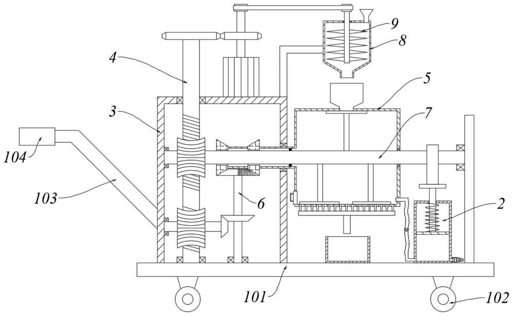
[0049] With reference to the accompanying drawings, a drying device for recycling resin waste products includes a car body, a transmission box 3, a drying tank 5, a pulverizing bucket 8 and a ventilation assembly 2;
[0050] The vehicle body includes a vehicle panel 101 and a wheel 102 installed below the vehicle panel 101; the left part of the vehicle panel 101 is provided with a transmission box 3; the transmission box 3 is provided with a drive assembly 4 and a swing assembly 6, and the drive assembly 4 and the swing assembly 6 cooperate; The right side of the transmission box 3 is provided with a drying tank 5; the drying tank 5 is arranged horizontally, and a stirring assembly 7 is arranged inside; 5. The ventilation assembly 2 is arranged on the right side.
Embodiment 2
[0052] With reference to the accompanying drawings, a drying device for recycling resin waste products includes a car body, a transmission box 3, a drying tank 5, a pulverizing bucket 8 and a ventilation assembly 2;
[0053] The vehicle body includes a vehicle panel 101 and a wheel 102 installed below the vehicle panel 101; the left part of the vehicle panel 101 is provided with a transmission box 3; the transmission box 3 is provided with a drive assembly 4 and a swing assembly 6, and the drive assembly 4 and the swing assembly 6 cooperate; The right side of the transmission box 3 is provided with a drying tank 5; the drying tank 5 is arranged horizontally, and a stirring assembly 7 is arranged inside; 5. The ventilation assembly 2 is arranged on the right side.
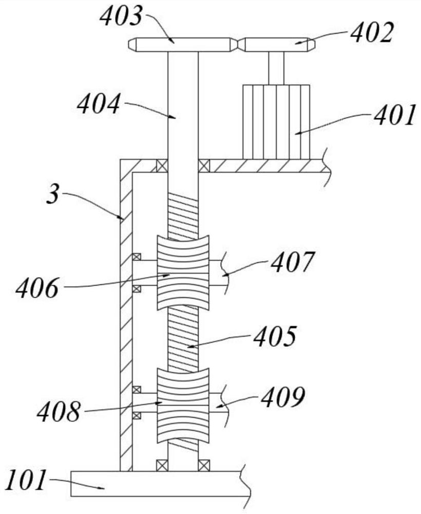
[0054] Wherein, the driving assembly 4 includes a servo motor 401, a No. 1 gear 402, a No. 2 gear 403, a No. 1 rotating shaft 404, a worm 405, a No. 1 worm wheel 406, an upper rotating shaft 407, a No. 2 worm wheel ...
Embodiment 3
[0076] Wherein, the same or corresponding components as in Embodiment 1 and Embodiment 2 adopt the reference numerals corresponding to Embodiment 1 and Embodiment 2. For the sake of brevity, only the differences from Embodiment 2 are described below. The difference between this embodiment and embodiment two is:
[0077] Transmission box 3 left side also is connected with push-pull assembly, and push-pull assembly comprises push-pull bar 103 and plastic cover 104, and push-pull bar 103 is a bent bar, and the right end is affixed to drive box 3, and left end horizontal setting and plastic cover 104 are housed.
[0078] Specifically, the plastic sleeve 104 is manually held to push the device to move through the push-pull assembly.
[0079] The electrical components mentioned above are all provided with a power supply, and the control means and circuits are all prior art, and will not be described in detail herein.
PUM
Abstract
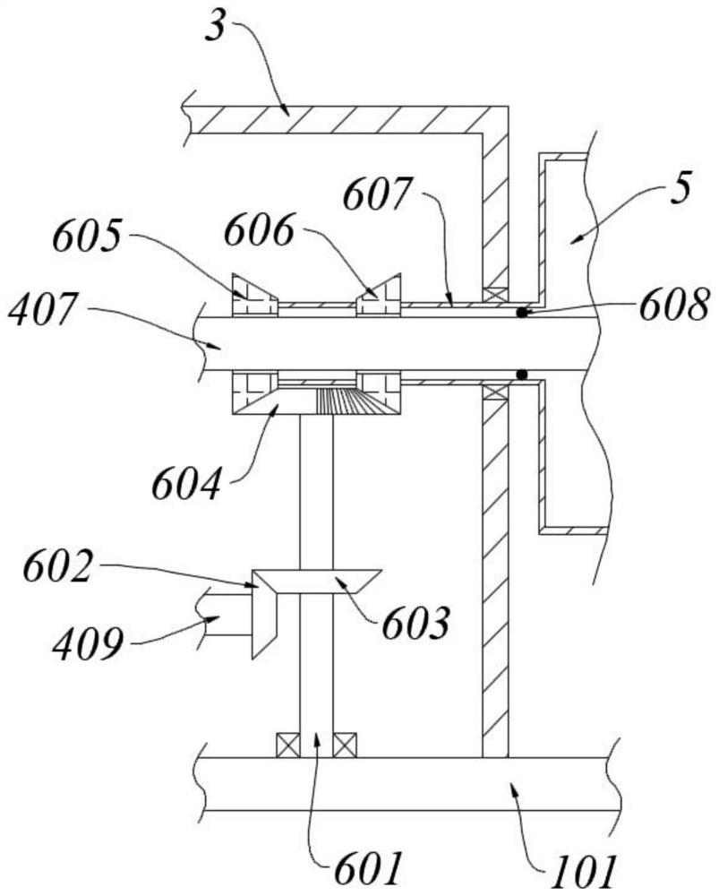
The invention relates to the technical field of resin waste recycling equipment, in particular to a drying device for resin waste recycling. A servo motor is adopted as drive powder, a first rotatingshaft is driven to rotate through gear transmission, so that a worm is driven to rotate. The worm drives a first worm wheel and a second worm wheel to rotate, and an upper rotating shaft and a lower rotating shaft are both made to rotate. For the upper rotating shaft, a stirring rod rotates along with the upper rotating shaft, on one hand, materials are stirred and scattered; and on the other side, scraper blades prevent materials from adhering to the wall; in cooperation air intake on the right side, the materials are in full contact with the dry air, so that moisture is taken away. For the lower rotating shaft, the lower rotating shaft drives a first bevel gear to rotate, a second rotating shaft is made to rotate through transmission of the bevel gear, an incomplete bevel gear rotates along with the rotating shaft and is sequentially meshed with a left bevel gear and a right bevel gear, so that a shaft sleeve generates reciprocating rotation, then a dissolution tank is driven to swing in a reciprocating manner, a shaking function is generated on the materials in the dissolution tank, centrifugal force is generated, and then moisture can be conveniently thrown into a water discharge pipe and discharged into a water collecting tank.
Description
technical field [0001] The invention relates to the technical field of recycling equipment for resin waste products, in particular to a drying device for recycling resin waste products. Background technique [0002] Resin usually refers to an organic polymer that softens or melts after being heated, has a tendency to flow under external force when softened, and is solid, semi-solid, or sometimes liquid at room temperature. Broadly defined, any polymer compound that can be used as a raw material for plastic products is called a resin. [0003] Synthetic resin is the basic raw material for the manufacture of plastics, synthetic fibers, coatings, adhesives, insulating materials, etc. Resin is currently used in a huge amount, which also causes the amount of resin waste to increase year by year, which should be recycled. [0004] When the resin is recycled, it must be cleaned first, which makes the resin more or less watery and needs to be dried. In the prior art, there are fe...
Claims
Application Information
Patent Timeline
Application Date:The date an application was filed.
Publication Date:The date a patent or application was officially published.
First Publication Date:The earliest publication date of a patent with the same application number.
Issue Date:Publication date of the patent grant document.
PCT Entry Date:The Entry date of PCT National Phase.
Estimated Expiry Date:The statutory expiry date of a patent right according to the Patent Law, and it is the longest term of protection that the patent right can achieve without the termination of the patent right due to other reasons(Term extension factor has been taken into account ).
Invalid Date:Actual expiry date is based on effective date or publication date of legal transaction data of invalid patent.

