
Complex part laser cladding interference detection and track correction method

A laser cladding and interference detection technology, applied in special data processing applications, instruments, electrical digital data processing, etc., can solve problems such as interference between laser beams and other parts, damage to parts or laser equipment, etc. The effect of processing safety

Active Publication Date: 2019-12-06
XINJIANG UNIVERSITY
View PDF5 Cites 4 Cited by
  • Summary
  • Abstract
  • Description
  • Claims
  • Application Information

AI Technical Summary

Problems solved by technology

[0004] The present invention provides a laser cladding interference detection and trajectory correction method for complex parts, which overcomes the shortcomings of the prior art and can effectively solve the problem that the existing laser cladding trajectory planning method is prone to interference between the laser beam and other parts Phenomena, problems that cause damage to parts or laser equipment

Method used


Image

  • Complex part laser cladding interference detection and track correction method
  • Complex part laser cladding interference detection and track correction method
  • Complex part laser cladding interference detection and track correction method

Examples


Embodiment 1

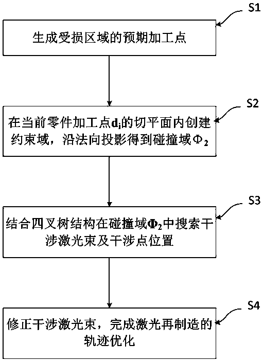
[0049] Embodiment 1: as attached figure 1 As shown, the complex parts laser cladding interference detection and trajectory correction method includes the following steps:

[0050] S1, generate the expected processing points of the damaged area, that is, generate the expected scanning path point set of the laser robot;

[0051] S2, at the current part processing point d i Create a constraint domain in the tangent plane of , and project along the normal direction to get the collision domain Φ 2 ;

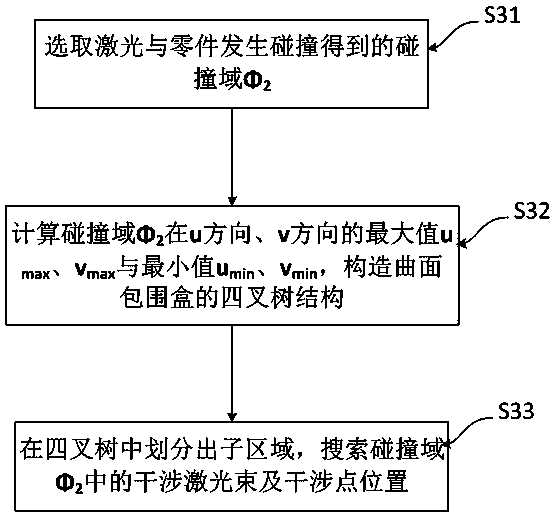
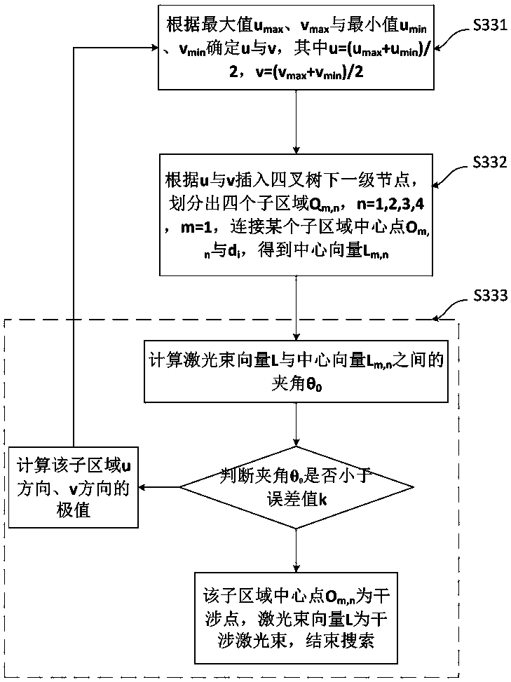
[0052] S3, combining the quadtree structure in the collision domain Φ 2 Quickly search for interfering laser beams and interfering point positions;

[0053] S4, modifying the interfering laser beam to complete the trajectory optimization of laser remanufacturing.

[0054] The invention creates a constraint domain in the tangent plane of the current part processing point, projects along the normal direction to obtain the collision domain, and combines the quadtree structure to quick...

Embodiment 2

[0081] Embodiment 2: as attached figure 1 , 11 , 12, taking the repair of the high-pressure steam valve in the boiler pipeline of a petrochemical plant as an example, the damaged area is the curved surface at the bottom of the part, as shown in the attached Figure 11 ; Establish a three-dimensional model of the damaged part and use the above method for laser beam interference detection. It is observed that there is laser interference in the boundary area of ​​​​the outlet at the top of the valve, and it is corrected immediately to obtain an effective laser beam. Carry out the actual processing and comparison of laser cladding, Figure 12 a is the morphology of the damaged area, Figure 12 b is the coating morphology after cladding, it can be found that the surface of the cladding layer is smooth without obvious cracks, and the effect is good, thus proving that the present invention has high practicability and reliability.


PUM


Abstract

The invention relates to the technical field of laser cladding, in particular to a laser cladding interference detection and track correction method for complex parts. The method comprises the following steps: S1, generating an expected processing point of a damaged area; S2, creating a constraint domain in the tangent plane of the current part machining point di, and obtaining a collision domainphi2 through normal projection; S3, searching an interference laser beam and an interference point position in a collision domain phi2 in combination with a quadtree structure; and S4, correcting theinterference laser beam, and completing track optimization of laser remanufacturing. According to the method, a constraint domain is created in a tangent plane of a current part machining point; projecting along the normal direction is performed to obtain a collision domain; interference laser beams and interference point positions are quickly searched in a collision domain in combination with a quadtree structure; and according to the laser remanufacturing method, posture correction is carried out on the interference laser beam, track optimization of laser remanufacturing is completed, and therefore the phenomenon that the laser beam interferes with other parts is avoided, the parts and laser equipment are protected, the application range of the laser remanufacturing technology is widened, and machining safety is improved.

Description

technical field [0001] The invention relates to the technical field of laser cladding, and relates to a laser cladding interference detection and trajectory correction method for complex parts. Background technique [0002] In order to meet the reliability requirements of parts in the field of industrial manufacturing, more and more parts with complex structures are used in actual production and processing. The manufacturing cost of complex structural parts is high, and if the work is damaged under harsh working conditions, if it is directly discarded, it will cause waste of resources. With the advantages of high precision, high integration and high applicability, laser additive remanufacturing technology has become an emerging technology in the field of additive intelligent manufacturing, which is of great significance to the establishment of an energy-saving and emission-reducing environment-friendly society. [0003] The quality of the laser cladding layer is affected by...

Claims


Application Information

Patent Timeline
Patent Type & Authority Applications(China)
IPC IPC(8): G06F17/50
CPCY02P10/25
Inventor 孙文磊刘金朵黄勇黄海博
Owner XINJIANG UNIVERSITY
Learn More