

Pointer type instrument automatic reading system and reading method based on space-time image
An automatic reading, pointer technology, applied in the direction of instruments, character and pattern recognition, computer parts, etc., can solve the problems of low automatic reading accuracy, complex image background information, detection of pointer position changes, etc., to achieve dynamic online Automatic reading, simple image processing algorithm, and the effect of improving detection speed
- Summary
- Abstract
- Description
- Claims
- Application Information
AI Technical Summary
Problems solved by technology
Method used
Image


Examples
Embodiment 1
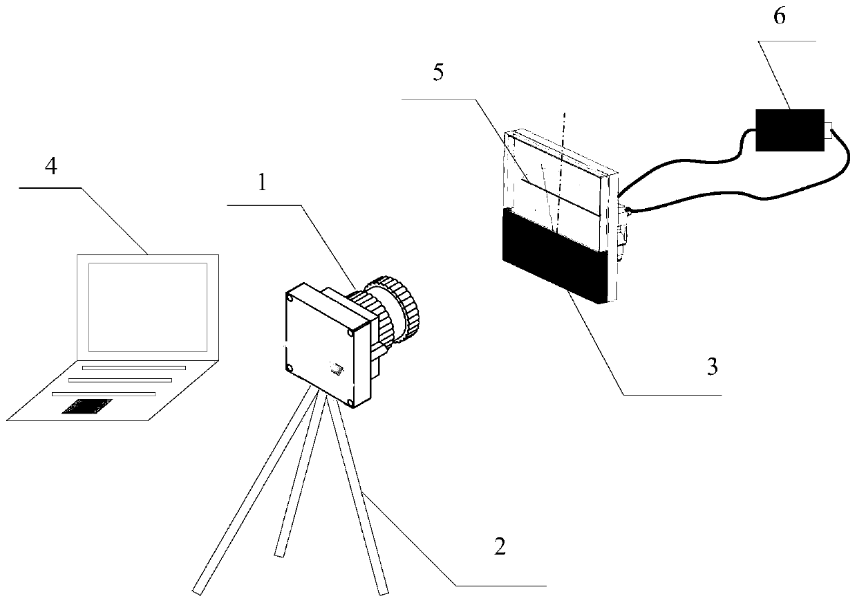
[0063] Such as figure 1 Shown, the pointer instrument automatic reading system based on spatio-temporal image of the present invention, comprises:
[0064] Line array camera, used to collect space-time images of pointer changes;
[0065] The tripod is used to fix the line array camera so that the collection area of the line array camera is facing the pointer instrument, and the collection line area is perpendicular to the center line of the pointer instrument panel;
[0066] Pointer instrument, used to indicate the reading of the voltage and current of the power supply to be tested;
[0067] The computer is used for image processing, extracting the center position of the pointer, and reading the pointer meter according to the prior information.
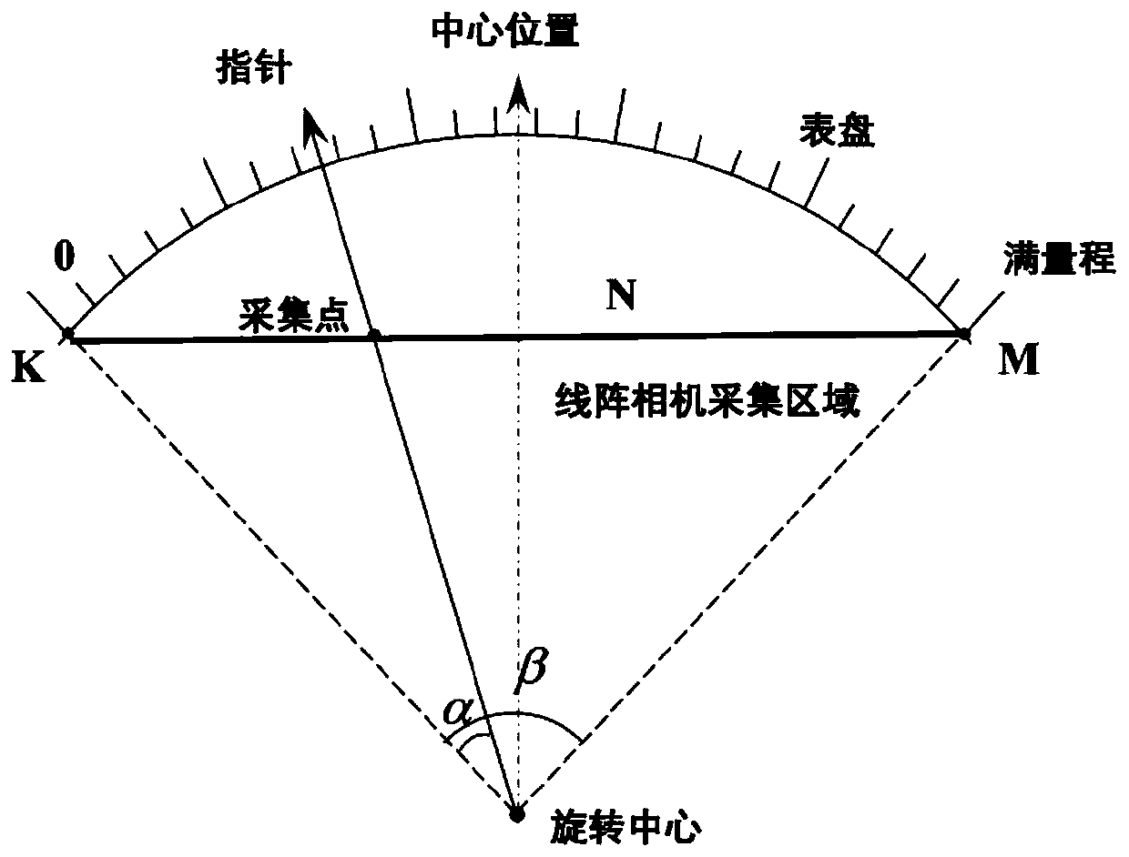
[0068] It should be noted that: if figure 2 The schematic diagram and geometric relationship diagram of the pointer instrument panel are shown. in:
[0069] The spatio-temporal image information collected by the line array cam...
Embodiment 2
[0072] Such as Figure 9 As shown, the reading method of the pointer instrument automatic reading system based on the spatio-temporal image of the present invention comprises the following steps:
[0073] S1: Acquisition of spatio-temporal images:
[0074] S11: Construction of the automatic reading system: fix the line-scan camera on the tripod, and set the line-scan camera to be detected by the pointer instrument, the collection line area of the line-scan camera is perpendicular to the pointer at the center, and the line-scan camera is connected to the computer ,Such as figure 1 and figure 2 shown;
[0075] S12: Collect spatio-temporal images, including the following situations:
[0076] Situation 1: Acquire the space-time image of the pointer at the zero point: short-circuit the input terminal of the pointer instrument, use a line array camera to collect the space-time image of the pointer at the zero point, and store it in the computer for image processing. The zero ...
Embodiment 3
[0108] The present invention will be explained below in conjunction with specific data.
[0109] image 3 The zero point of the middle pointer is K=139.2, Figure 4 The full scale point of the middle pointer is M=1491.9, Figure 6 The pointer is at 12.27V.
[0110] In this example, the total number of pixels in the pointer rotation area is N=1352.7, the full-scale rotation angle of the pointer instrument panel is β=90°, and the full-scale reading of the instrument panel is range=FS=20V. The voltage resolution of each pixel is Re=FS / N=0.015V.
[0111] Comparison table between the present invention and visual reading results
[0112] Way First reading (V) Second reading (V) Automatic reading of spatiotemporal images 4.46 12.27 visual reading 4.4 12.3 error 0.06 0.03
[0113] It can be seen from the above table that the automatic reading method of pointer meters based on spatio-temporal images provided by the present invention is not on...
PUM
 Abstract
Description
Claims
Application Information