Built-in part array assembling machine and production method of motor stator using same

A built-in, assembly machine technology, applied in the manufacture of motor generators, stator/rotor bodies, electrical components, etc., can solve the problems of poor quality stability, poor assembly accuracy, and high assembly costs

Pending Publication Date: 2019-12-06
UNIV OF ELECTRONICS SCI & TECH OF CHINA ZHONGSHAN INST
View PDF0 Cites 1 Cited by
  • Summary
  • Abstract
  • Description
  • Claims
  • Application Information

AI Technical Summary

Problems solved by technology

[0002] In some production processes that need to mount other parts in a circular array inside the shell, such as some motor stators, where the motor casing is the shell and the permanent magnets are the array parts, these array parts need to be placed in a circular array The method is mounted and fixed on the inner wall of the housing. The usual practice is to glu

Method used


Image

  • Built-in part array assembling machine and production method of motor stator using same
  • Built-in part array assembling machine and production method of motor stator using same
  • Built-in part array assembling machine and production method of motor stator using same

Examples


Embodiment Construction

[0044] The present invention will be further described below in conjunction with accompanying drawing:

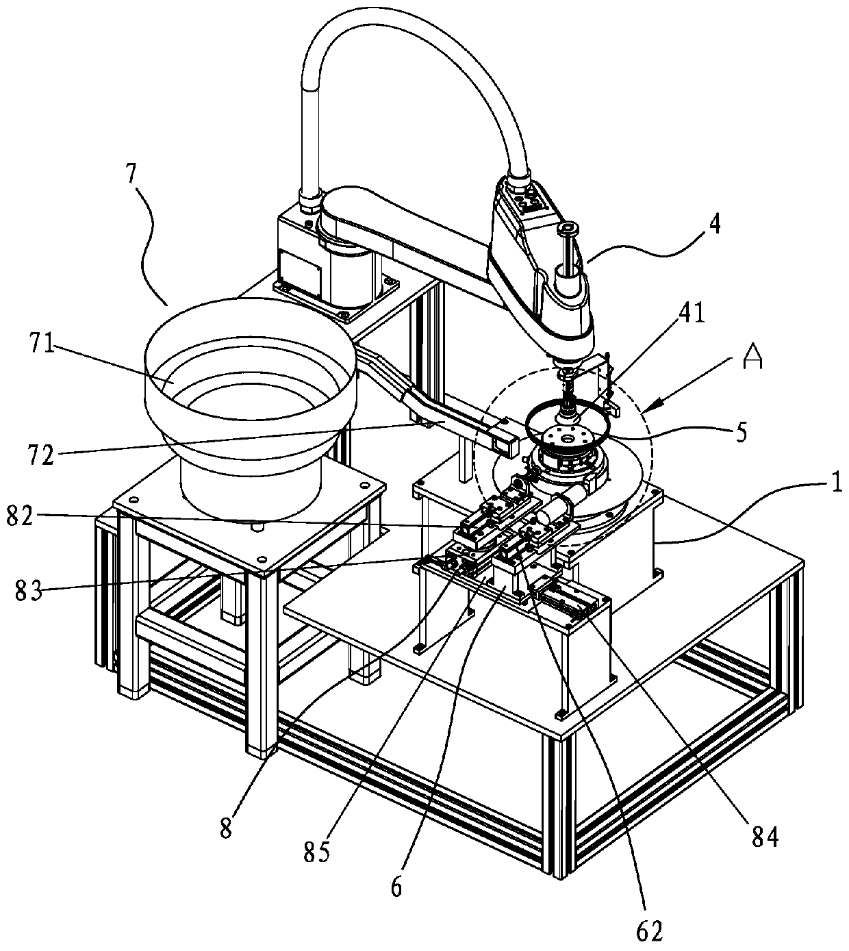
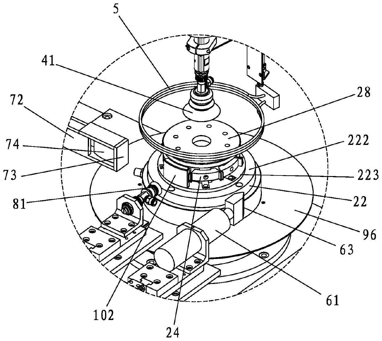
[0045] Such as Figure 1 to Figure 9 The built-in part array assembly machine shown includes a bracket 1. A turntable 21 capable of rotating 360° is provided on the bracket 1. A positioning plate 22 is fixed on the turntable 21. A plurality of The sliding support block 23 that can expand and shrink relative to the center of rotation of the positioning disc 22, then each sliding support block 23 can slide close to or slide away from the center of rotation of the positioning disc 22. One side is provided with a clamp 24 for clamping the array parts 102, the number of the sliding support blocks 23 and the clamps 24 is equal to the number of the array parts 102 in the same circumferential direction, and a plurality of the sliding support blocks 23 surround the positioning plate The center of rotation of 22 is evenly distributed and can be used for the shell 101 to buckle on th...


PUM


Abstract

The invention discloses a built-in part array assembling machine. Slide support blocks and clamps arranged on a positioning plate are driven to rotate by a rotating table. The rotating empty clamps are mounted on the array parts one by one by a material taking device. Glue is applied to the array parts by a glue applying device. A shell is grasped by a manipulator and buckled on the outer side ofthe assembled array parts. The slide support block is driven by the downward movement of a pressing block driven by an open cylinder to open outwardly and stick to the inner wall of the shell with thearray parts mounted on the clamps and then the glue is cured by heating through a heating ring. The opening cylinder drives the pressing block to move upward after sticking firmly, the rolling pieceon the pressing block releases the top pressure on the slide support block and the slide support block shrinks and moves inward under the action of a compression spring to drive the clamp to release the magnet piece. The automatic assembling of the built-in array parts and the shell can be realized, the structure is simple and the equipment occupation space is small. The invention also discloses aproduction method of the motor stator by using the assembling machine. The assembling efficiency is high and the quality stability is good.

Description

【Technical field】 [0001] The invention relates to a built-in component array assembly machine, and also relates to a production method of a motor stator using the assembly machine. 【Background technique】 [0002] In some production processes that need to mount other parts in a circular array inside the shell, such as some motor stators, where the motor casing is the shell and the permanent magnets are the array parts, these array parts need to be placed in a circular array The method is mounted and fixed on the inner wall of the housing. The usual practice is to glue the permanent magnets one by one and assemble them in the motor casing, and use the jig to position the pasted permanent magnets in the specific position in the motor casing. In the position, it is not removed until the glue is dry. Its disadvantages are low assembly efficiency and high assembly cost; the other is poor assembly accuracy and poor quality stability. [0003] The present invention is made aiming a...

Claims


Application Information

Patent Timeline
IPC IPC(8): H02K15/03
CPCH02K15/03
Inventor 祝胜光陈良福李江
Owner UNIV OF ELECTRONICS SCI & TECH OF CHINA ZHONGSHAN INST
Why Eureka
Try Eureka