Turnover discharge mechanism of green leaf rocking machine
A technology of unloading mechanism and shaking machine, which is applied in the directions of loading/unloading, emptying container, bottle filling, etc., can solve the problems of inconvenient tea shaking operation and low processing efficiency of shaking equipment, so as to ensure the unloading operation. Effect
Inactive Publication Date: 2019-12-10
安徽岩上松现代农业有限公司
0 Cites 2 Cited by
AI-Extracted Technical Summary
Problems solved by technology
Most of the existing shakers are horizontally arranged drum equipment. When the fresh leaves are actually put in, the door on the outer wall of the drum is opened, and then the fresh leaves are put into the drum, and the motor is started, so as to realize the rotation of the drum, and the drum reciprocates. After t...
Method used
Above-mentioned shaking green tube 10 is preferably a bamboo strip tube, so that the inwall of shaking green tube 10 has a special flat state, when implementing the shaking green processing of fresh leaves, it can effectively ensure the effective destruction of cell walls in fresh leaves , so that the fresh leaves release the liquid juice, so that the fragrance of the tea leaves can be fully released when the tea leaves are fried after being shaken;
[0017] In order to improve the intensity of shaking the green tube 10, the tube prepared by the bamboo str...
Abstract
The invention relates to a turnover discharge mechanism of a green leaf rocking machine. The turnover discharge mechanism comprises a green leaf rocking cylinder, wherein openings in both ends of thegreen leaf rocking cylinder respectively function as a feeding hole and a discharge hole; the cylinder wall of the discharge end of the green leaf rocking cylinder is arranged on a rotating base in ahinged manner; the green leaf rocking cylinder is connected with a discharge mechanism; the discharge mechanism drives the green leaf rocking cylinder to rotate around a hinging shaft and enables theopening in the discharge end to face downwards; and a vibration mechanism is additionally arranged on the outer wall of the green leaf rocking cylinder. When the opening in the discharge end of the green leaf rocking cylinder faces downwards, the outer wall of the green leaf rocking cylinder is vibrated through the vibration mechanism; after green leaf rocking operation is completed, the dischargemechanism is powered on, the green leaf rocking cylinder is rotated around a rotating base in a position of the discharge end, the opening of the green leaf rocking cylinder faces downwards in an inclined manner, and thus automatic discharge operation of fresh leaves after green leaf rocking treatment is achieved; and in discharge operation, the green leaf rocking cylinder is rotated in a hingedmanner through the discharge mechanism, the opening of the green leaf rocking cylinder faces downwards in an inclined manner, the vibration mechanism is powered on, the green leaf rocking cylinder isvibrated, then vibration of the fresh leaves in the green leaf rocking cylinder can be achieved, and discharge operation of the fresh leaves in the green leaf rocking cylinder can be ensured.
Application Domain
Pre-extraction tea treatmentBottle emptying +1
Technology Topic
EngineeringGreen leaf
Image
Examples
- Experimental program(1)
Example Embodiment
[0012] In order to make the objects and advantages of the present invention clearer, the present invention will be described in detail below in conjunction with the examples. It should be understood that the following words are only used to describe one or several specific implementation modes of the present invention, and do not strictly limit the protection scope of the specific claims of the present invention. As used herein, the terms "parallel" and "perpendicular" are not limited to their strict geometric definitions, but include reasonable and inconsistent tolerances for machining or human error; The specific characteristics of:
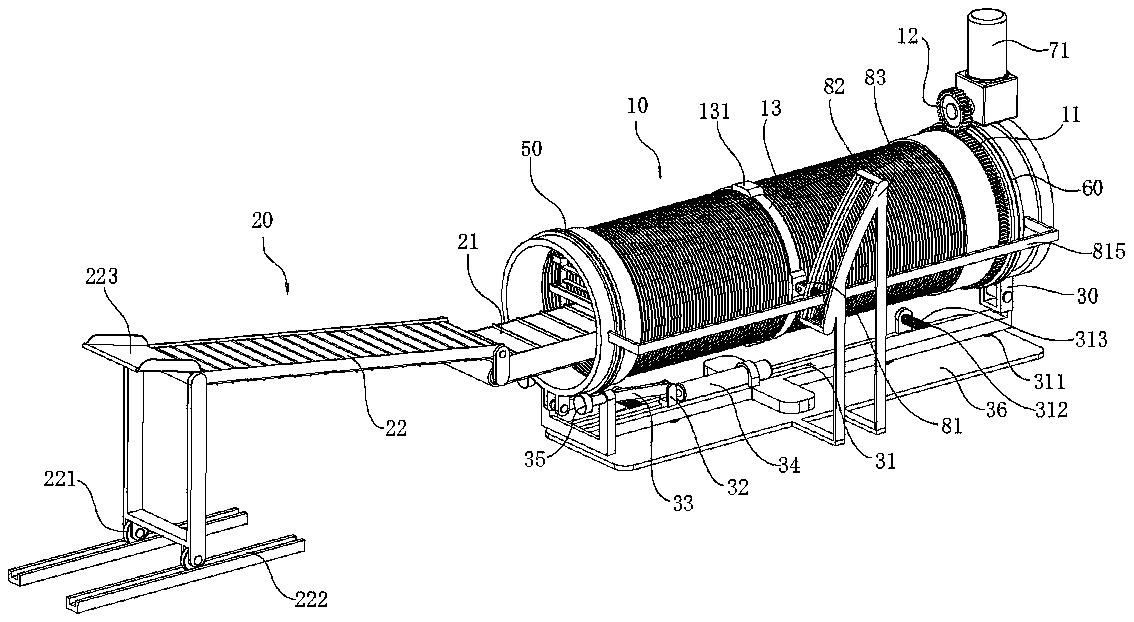
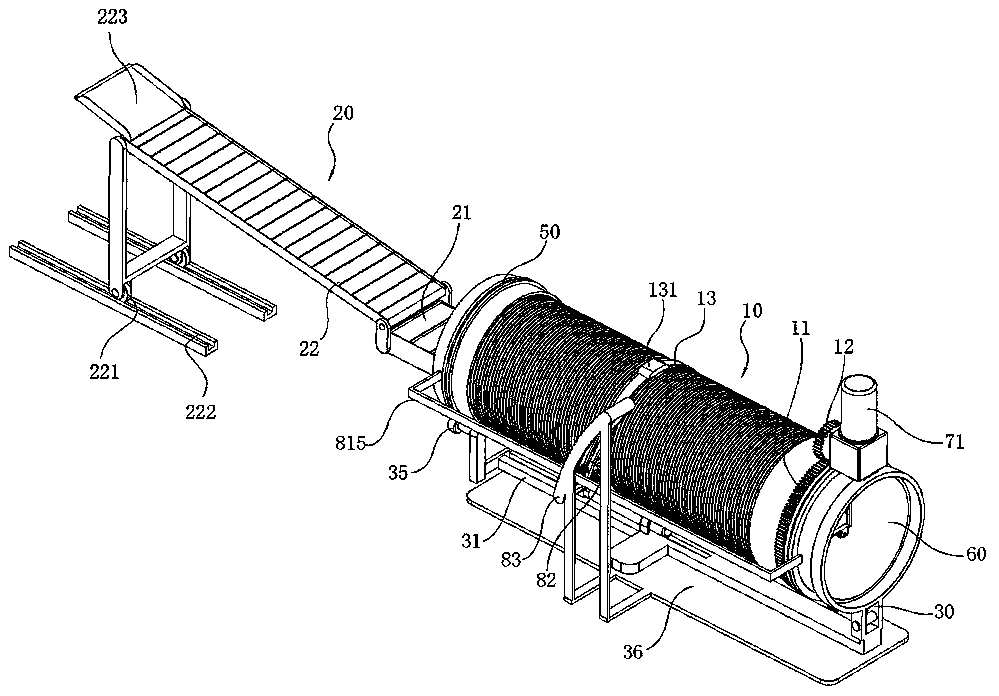
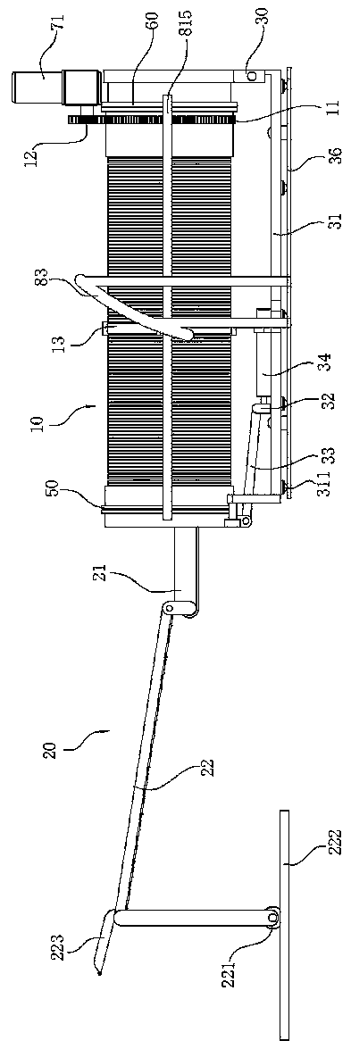
[0013] Below in conjunction with the whole automatic loading and unloading shaking green machine, the turning and unloading mechanism of the shaking green machine of the present invention is described in detail:
[0014] An automatic loading and unloading shaker, comprising a shaker tube 10, the openings at both ends of the shaker tube 10 form a feed port and a discharge port respectively, and the feed port of the shaker tube 10 is provided with a feeding device 20. The discharge end of the feeding device 20 extends into the chamber of the shaker cylinder 10, and the wall of the discharge end of the shaker cylinder 10 is hingedly arranged on the rotating seat 30, and the hinge shaft is horizontal and parallel to the shaker cylinder 10. The length direction of the blue cylinder 10 is vertical, and the shaker cylinder 10 is connected with the unloading mechanism, and the discharge mechanism drives the shaker cylinder 10 to rotate around the hinge shaft and make the discharge end cylinder mouth downward;
[0015] combine Figure 1 to Figure 4 As shown, during the actual shaking operation, fresh leaves are put into the feeding device 20, and the feeding device 20 guides the fresh leaves into the shaking green cylinder 10, and the driving mechanism is started to implement the rotation of the shaking green cylinder 10. The rotation of the green tube 10 is a reciprocating rotation mode. When the green tube 10 is rotated in one direction for one end of time, it is rotated in the opposite direction for one end of time to improve the effect of shaking green leaves on fresh leaves, so that part of the cell walls of fresh leaves are destroyed. Release the fragrance of fresh leaves to improve the quality of tea leaves in the later stage. After the shake operation is completed, start the unloading mechanism to make the shaker 10 rotate around the rotating seat 30 at the discharge end, so that the mouth of the shaker 10 is inclined The disposal is downward to realize the automatic unloading operation of the fresh leaves after shaking green treatment, and the green shaking machine can significantly improve the processing efficiency of fresh leaves;
[0016] The above-mentioned shaking green tube 10 is preferably a bamboo strip tube, so that there is a special flat state in the inner wall of the shaking green tube 10, and when implementing the shaking green treatment of fresh leaves, it can effectively ensure the effective destruction of the inner cell wall of the fresh leaves, so that the fresh leaves can be effectively destroyed. The leaves release the liquid juice, so that the fragrance of the tea leaves can be fully released when the tea leaves are fried after being shaken;
[0017] In order to improve the intensity of shaking the green tube 10, the tube prepared by bamboo strips is placed in the steel cage to realize the installation and fixing of the bamboo strips tube.
[0018] In order to make the tea leaves introduced into the shaking green cylinder 10 evenly distributed along the length direction, ensure the shaking green effect on fresh leaves, so that most of the fresh leaves can contact and rub against the shaking green cylinder 10, the outlet of the feeding device 20 The position of the material opening is provided with a uniform material mechanism 40, which is used to uniformly distribute the fresh leaves exported from the outlet of the feeding device 20 along the length direction of the shaker cylinder 10;
[0019] The equalizing mechanism 40 is started, so that the tea leaves are evenly distributed along the length direction of the shaker cylinder 10, thereby ensuring the shaker effect on the tea leaves.
[0020] In order to ensure the effective unloading of the lifted shaker 10 so that the tea leaves in the shaker 10 can be effectively exported, the outer wall of the shaker 10 is also provided with a vibration mechanism, and the unloading mechanism drives the shaker 10 When rotating around the hinged shaft and making the mouth of the discharge end face down, the vibrating mechanism implements vibrations to the outer wall of the shaker cylinder 10;
[0021] When implementing the unloading operation, the unloading mechanism makes the shaker tube 10 rotate around the hinge of 30, and then the mouth of the shaker tube 10 is tilted downward, and the vibration mechanism is activated to make the shaker tube 10 vibrate, thereby realizing the vibration of the shaker tube 10. The vibration of the fresh leaves in the green tube 10 is to ensure the unloading operation of the fresh leaves in the blue tube 10.
[0022] combine Figure 8 As shown, in order to guide the fresh leaves into the cylinder cavity of the shaking green cylinder 10, and realize the uniform distribution of the fresh leaves, the feeding device 20 includes a first conveyor belt 21 arranged horizontally, and the first conveyor belt 21 is introduced into the cylinder cavity of the shaking cylinder 10, the uniform material mechanism 40 includes a uniform brush plate 41 arranged in the cylinder cavity of the shake cylinder 10, the uniform material brush plate 41 is arranged in the length direction, and the uniform material brush The plate 31 approaches or moves away from the first conveyor belt 21 and reciprocates along the width direction of the first conveyor belt 21;
[0023] Fresh leaves are transported by the first conveyor belt 21, so that the fresh leaves are arranged along the upper surface of the first conveyor belt 21, and when the first conveyor belt 21 is transported along the shaker cylinder 10, and the fresh leaves are guided to When the first conveyor belt 21 is at the exit position, start the uniform brush plate 41 to move along the width direction of the first conveyor belt 21, thereby driving the tea leaves arranged on the first conveyor belt 21 into the shaker tube 10, And the fresh leaves can be evenly arranged along the length direction of the inner wall of the shaker tube 10;
[0024] In order to ensure that the tea leaves on the first conveyor belt 21 are evenly arranged, the feed end of the first conveyor belt 21 is connected with the outlet of the vibrating distribution machine. The vibrating distribution machine is a common discharge machine, and the vibrating distribution machine includes a vibrating plate A vibrating motor is arranged on the vibrating plate, and by starting the vibrating motor, the fresh leaves are moved along the vibrating plate, and then the guiding of the fresh leaves is realized, and the fresh leaves are gradually transported to the first conveyor belt 21, and the fresh leaves are comparatively Evenly arranged on the rotating first conveyor belt 21, to realize the prior distributing operation of fresh leaves, when the fresh leaves are shaken, the vibrating distribution machine stops, and the first conveyor belt 21 goes to the corresponding shutdown , to provide enough shaking green time for fresh leaves.
[0025] Specifically, combined with Figure 8 In the enlarged view, one end of the uniform material brush plate 41 is connected to the piston of the rodless cylinder 42, the piston rod of the rodless cylinder 42 is horizontal and perpendicular to the length direction of the shaker cylinder 10, and the rodless cylinder 42 The two ends of the piston rod are connected with the two sides frames of the first conveyor belt 21 through the lifting bracket 43, and the lifting bracket 43 is connected with the lifting unit, and the lifting unit drives the lifting bracket 43 to move vertically;
[0026] After the fresh leaves are close to moving to the discharge end position of the first conveyor belt 21, the first conveyor belt 21 is stopped, and then the rodless cylinder 42 is started, so that the uniform material brush plate 41 moves along the width direction of the first conveyor belt 21, Then the tea leaves on the first conveyor belt 21 are pushed into the shaker tube 10 by the bristles of the uniform material brush plate 41, so as to realize uniform distribution and feeding of fresh leaves;
[0027] While the above-mentioned equalizing brush plate 411 is pushing the fresh leaves on the first conveyor belt 21, the lifting unit first moves vertically in conjunction with the lifting bracket 43, so that the lower bristles of the equalizing brush plate 411 are in contact with the first conveyor belt 21. The upper belt surface of the first conveyor belt 21 is abutted against, thereby ensuring that the tea leaves on the first conveyor belt 21 are effectively pushed into the shaker cylinder 10 .
[0028] Specifically, combined with Figure 8 In the enlarged view, in order to realize the vertical lifting of the uniform brush plate 411, the lifting unit includes vertical slide bars 211 vertically arranged on the frames on both sides of the first conveyor belt 21, and the lifting bracket 32 is slidably arranged on On the vertical slide bar 211, the upper end of the vertical slide bar 211 is set in a "T" shape, and the vertical slide bar 211 is provided with a return spring 212, and the upper and lower ends of the return spring 212 are connected with the lifting bracket respectively. 43 and the frames on both sides of the first conveyor belt 21 are against each other, and the frame on one side of the first conveyor belt 21 is also extended with a lifting drive plate 213, and the piston of the rodless cylinder 42 is rotatably provided with a lifting drive plate 213. Driving wheel 44, the wheel core of the lifting driving wheel 44 is horizontal and parallel to the tube length direction of the shaking green tube 10, the upper rim of the lifting driving wheel 44 abuts against the lower plate surface of the lifting driving plate 213, and the lifting One end of the lower plate surface of the drive plate 213 is low and the other end is high;
[0029] The above-mentioned lifting drive plate 213 is fixedly arranged. When the rodless cylinder 42 is started, the piston moves along the piston rod, so that when the rim of the lifting driving wheel 44 abuts against the lower surface of the lifting driving plate 213, when the lifting driving wheel 44 After moving to the lower lower plate surface section of the lifting drive plate 44, the uniform material brush plate 411 is lowered and the operation of rushing the tea leaves is implemented. After the rodless cylinder 42 is reset, under the action of the return spring 212, the uniform material brush plate The plate 411 is raised and reset, and then moved to the side of the first conveyor belt 21, so as to avoid the influence of the bristles of the uniform material brush plate 411 on the fresh leaf guide;
[0030] For the rotation drive of the shaker cylinder 10, the mouth of the feed end of the shaker cylinder 10 is connected to the turntable on one side of the first support bearing 50, and the turntable on the other side of the first support bearing 50 is connected to the discharge Mechanism connection, the cylinder mouth of the discharge end of the shaker cylinder 10 is connected with one side turntable of the second support bearing 60, and the other side turntable of the second support bearing 60 is hinged with the rotating seat 30;
[0031] combine figure 1 and figure 2 As shown, the two ends of the above-mentioned shaker cylinder 10 are respectively connected with the first support bearing 50 and the second support bearing 60, and the first support bearing 50 and the second support bearing 60 can be thrust bearings to realize the rotation of the shaker cylinder 10. Rotate the support so that the shaker 10 can rotate effectively;
[0032] In order to realize the support to the first conveyor belt 21 introduced into the shaker cylinder 10, and to avoid the interference of the first conveyor belt 21 when the shaker cylinder 10 rotates, the first conveyor belt 21 extends into the inside of the shaker cylinder 10 The frame is provided with a roller bracket 214, and the roller bracket 214 is rotatably provided with a supporting roller 215, the wheel core of the supporting roller 215 is horizontal and the rim is against the inner wall of the shaker tube 10;
[0033] The support roller 215 is used to abut against the inner wall of the shaker cylinder 10, so as not to affect the normal rotation of the shaker cylinder 10;
[0034] In order to realize stable support to the first conveyor belt 21, four support rollers 215 are arranged at intervals along the inner wall circumferential direction of the shaker cylinder 10, and the four support rollers 215 are connected to form a rectangle;
[0035] The above-mentioned supporting rollers 215 are respectively provided at the feeding end and the discharging end of the first conveyor belt 21 , so that the first conveyor belt 21 is supported at both ends to ensure effective support for the first conveyor belt 21 .
[0036] combine image 3 and Figure 4 As shown, in order to realize the effective unloading of the shaker cylinder 10, the unloading mechanism includes an unloading slide rail 31 connected to the rotating seat 30, and the unloading slide rail 31 is provided with an unloading slider 32, so The discharge slider 32 is hinged to one end of the discharge connecting rod 33, the other end of the discharge connecting rod 33 is hinged to the edge of the turntable on the other side of the first support bearing 50, and the hinges at both ends of the discharge connecting rod 33 The axis is horizontal and perpendicular to the length direction of the shaker cylinder 10, the discharge slider 32 is connected with the piston rod of the discharge cylinder 34, and the length direction of the discharge cylinder 34 is parallel to the shaker cylinder 10;
[0037] When the fresh leaves are positioned in the shaker cylinder 10 after the shaking process is completed, start the unloading oil cylinder 34, so that the unloading slide block 32 slides along the discharge slide rail 31, and then the unloading connecting rod 33 is linked to implement the adjustment of the shaker cylinder 10. The fixed turntable of the first supporting bearing 50 at the position of the feed end is lifted. When the shaker cylinder 10 is lifted, the outlet end of the shaker cylinder 10 is tilted downward, and the shaker cylinder 10 is started to rotate, thereby realizing the internal shaking of the shaker cylinder 10. The unloading operation of green tea leaves.
[0038] In order to realize the driving of the shaker cylinder 10, a driving motor 71 is arranged on the rotating disk hinged between the second support bearing 60 and the rotating seat 30, and a ring gear 11 is arranged on the outer wall of the mouth of the cylinder, and the ring gear 11 and the driving gear 12 Mesh, the drive motor 71 drives the drive gear 12 to rotate, the end of the discharge slide rail 31 is provided with two support rollers 35, the two support rollers 35 are parallel to the length direction of the shaker cylinder 10, and the two support rollers 35 are located on both sides of the turntable on the other side of the first support bearing 50, and the roller surfaces of the two support rollers 35 abut against or separate from the edge of the turntable on the other side of the first support bearing 50;
[0039] When implementing the rotation of the shaker cylinder 10, start the driving motor 71, so that the rotation action of the shaker cylinder 10 on the first support bearing 50 and the second support bearing 60 makes the drive motor 71 present a forward rotation and a period of time. Reversal of time, when the green shaking operation is completed, start the unloading oil cylinder 34 to realize the unloading operation of the fresh leaves in the green shaking cylinder 10, when the discharge end of the green shaking cylinder 10 is tilted downward, start to drive the green shaking The cylinder 10 continues to rotate to ensure that the fresh leaves in the shaker cylinder 10 can be exported from the shaker cylinder 10 smoothly.
[0040] In order to ensure the unloading reliability of fresh leaves, the vibrating mechanism includes a vibrating roller 81 arranged on the side of the shaker 10, the outer wall of the shaker 10 is provided with a vibrating ring 13, and the outer ring of the vibrating ring 13 Vibrating blocks 131 are arranged at intervals, and the rim of the vibrating roller 81 abuts against the outer wall of the vibrating ring 13;
[0041] combine Figure 4 and Figure 7 As shown, when the shaker cylinder 10 is in an inclined state, the shaker cylinder 10 rotates so that the vibrating ring 13 abuts against the vibrating roller 81, and when the vibrating roller 81 abuts and separates from the vibrating block 131 of the vibrating ring 13, the shaking The cylinder 10 vibrates and swings, thereby ensuring that the fresh leaves in the shaker cylinder 10 are effectively exported.
[0042] In order to support the vibrating roller 81, and make the vibrating roller 81 move along with the discharge deflection of the shaker cylinder 10, a sliding rod 811 is arranged on the roller bracket of the vibrating roller 81, and the sliding rod 811 is horizontal and parallel to the Shake blue cylinder 10 length direction vertical, described slide bar 811 is slidably arranged on the support carriage 82, and described support carriage 82 is provided with arc-shaped slide hole 821, and the center of circle where described arc-shaped slide hole 821 is located and shakes blue The hinge axis of the discharge end of the barrel 10 is concentric, and the sliding rod 811 is slidably arranged in the arc-shaped sliding hole 821;
[0043] combine Figure 7 In the enlarged view, a washer 812 is slidably arranged on the sliding rod 811, a drive ball 813 is provided at the end of the sliding rod 811 protruding from the arc-shaped sliding hole 821, and a compression spring 814 is set on the sliding rod 811. , the two ends of the compression spring 814 abut against the washer 812 and the rod end of the sliding rod 811 respectively, the driving ball 813 abuts against the surface of the driving limiting plate 83, and the driving limiting plate 83 is in contact with the arc-shaped The sliding holes 821 extend in the same direction and the thickness of the upper end surface is greater than the thickness of the lower end surface;
[0044] When the unloading mechanism drives the shaking cylinder 10 to rotate around the hinged shaft of the rotating seat 30, the interlocking vibrating roller 81 swings synchronously, so that the sliding rod 811 of the vibrating roller 81 rotates around the arc-shaped sliding hole 821, because the arc-shaped sliding hole 821 It is concentric with the hinge shaft of the rotating seat 30, so it can ensure that the vibrating roller 81 is at the position of the vibrating ring 13, and after the shaking cylinder 10 is rotated, the vibrating roller 81 can be effectively abutted against the vibrating ring 13;
[0045] combine Figure 7 In the enlarged view, when the shaker 10 is unloading, the sliding rod 811 is made to slide along the arc-shaped sliding hole 821, and the driving ball 813 at the rod end of the sliding rod 811 is made to abut against the driving limit plate 83, due to the driving limit The thickness of the bit plate 83 is high and thin, and when the driving roller 813 abuts against the thicker section of the upper end, the compression spring 814 is compressed, and then the vibrating roller 81 is abutted against the vibrating ring 13, and the shaking cylinder 10 rotates to Ensure the rocking of the shaking blue cylinder 10. After the unloading is completed, the shaking green cylinder 10 is reset and level, and the compression spring 814 is reset, so that the driving roller 813 is far away from the vibrating ring 13, and does not affect the normal rotation of the shaking blue cylinder 10, so as to realize Shaking green operation on fresh leaves.
[0046] In order to realize the sliding support and guidance of the sliding rod 811, a support frame 815 is extended at the protruding end of the sliding rod 811. The support frame 815 extends along the length of the shaker cylinder 10 and the extension ends at both ends face the shaker cylinder 10. The cylinder wall of the support frame 815, the extension ends at both ends of the support frame 815 form a sliding fit with the fixed turntable outer wall of the first support bearing 50 and the second support bearing 60 respectively, and the sliding direction of the support frame 815 is horizontal and the length of the shaker cylinder 10 is Direction is vertical.
[0047] combine image 3 and Figure 4 As shown, in order to avoid shaking of the shaker 10, a plurality of moving balls 311 are equidistantly distributed on the lower surface of the discharge slide rail 31, and the moving balls 311 are rollingly arranged on the fixed base plate 36. One side of the unloading slide rail 31 is provided with a reset lever 312, the rod end of the reset lever 312 stretches out from one side of the fixed base plate 36, the reset lever 312 is sleeved with a spring 313, and the two ends of the spring 313 They are respectively abutted and connected with one side of the fixed base plate 36 and one side of the discharge slide rail 31 .
[0048] In order to realize the continuous feeding of fresh leaves, the feeding device 20 also includes a second conveyor belt 22, the discharge end of the second conveyor belt 22 is located above the feed end of the first conveyor belt 21, and the The frame of the second conveyor belt 22 is hinged to the feed end frame of the first conveyor belt 21 , and the hinge axis of the second conveyor belt 22 is horizontal and perpendicular to the length direction of the second conveyor belt 22 .
[0049] Since the first conveyor belt 21 is lifted, the second conveyor belt 22 is linked to rotate, and the second conveyor belt 22 is moved along the length direction. On the support frame, a guide roller 221 is arranged below the support frame, the wheel core of the guide roller 221 is horizontal and perpendicular to the second conveyor belt 22, and the guide roller 221 is rollingly arranged on the track 222, and the second conveyor belt The feed end of the belt 22 is hingedly provided with a slide plate 223, and the plate end of the slide plate 223 is attached to the upper belt surface of the feed end of the second conveyor belt 22, and the slide plate 223 is connected with the discharge end of the vibrating machine distribution machine. ;
[0050] When the shaking cylinder 10 is unloaded and lifted, the second conveyor belt 22 is rolled along the track 222 to avoid rotation of the first conveyor belt 21;
[0051] One end of the above-mentioned slide plate 223 is hinged and the hinge axis is perpendicular to the length direction of the second conveyor belt 22. When the fresh leaves derived from the discharge end of the vibrator distribution machine are exported to the slide plate 223, when the second conveyor belt 22 is supported around the feed end During the process of rack rotation and lifting, the slide plate 223 is always connected with the feeding end of the second conveyor belt 22, so as to avoid the fresh leaves from falling on the slide plate 223.
[0052] combine Figure 1 to Figure 4 Shown, the tealeaves shakes green method in detail below, and described tealeaves shakes green method comprises the steps:
[0053] A. Put the fresh leaves on the vibrating distribution machine, so that the tea leaves are guided to the slide plate 223 and then to the second conveyor belt 22;
[0054] B, the second conveyor belt 22 gradually guides the fresh leaves to the first conveyor belt 21, starts the first conveyor belt 21, so that the fresh leaves are positioned along the upper belt surface of the first conveyor belt 21;
[0055] C. Start the rodless cylinder 42, and move the even material brush plate 41 along the width direction of the first conveyor belt 21 to drive the tea leaves on the first conveyor belt 21 into the shaker tube 10. Then, the rodless cylinder 42 reset;
[0056] D, start drive motor 71, make shaking green tube 10 rotate on the first support bearing 50 and the second support bearing 60, realize the operation of shaking green leaves to fresh leaves;
[0057] E, setting the forward rotation time and the reverse rotation time of the drive motor 71, to implement the forward and reverse circular reciprocating rotation of the shaker cylinder 10;
[0058] F. After the shaker cylinder 10 completes the shaking of fresh leaves, start the unloading oil cylinder 34, so that the unloading slider 32 slides along the unloading slide rail 31, thereby linking the unloading connecting rod 33 to rise and fall, so as to Even shaking the green tube 10 rotates around the rotating seat 30 at the mouth of the tube to implement the unloading of fresh leaves;
[0059] G. Start the drive motor 71 to make the shaker 10 rotate, and make the vibrating ring 13 of the shaker 10 abut against the vibrating roller 81 to shake the shaker 10. After shaking the shaker 10, The tea leaves are exported from the mouth of the tube;
[0060] H. The unloading oil cylinder 34 is reset, and the shaking green cylinder 10 is arranged horizontally with the cylinder core level, and steps A to G are repeated to complete the shaking green leaves operation.
PUM


Description & Claims & Application Information
We can also present the details of the Description, Claims and Application information to help users get a comprehensive understanding of the technical details of the patent, such as background art, summary of invention, brief description of drawings, description of embodiments, and other original content. On the other hand, users can also determine the specific scope of protection of the technology through the list of claims; as well as understand the changes in the life cycle of the technology with the presentation of the patent timeline. Login to view more.