Novel medical annular conveying line device

A circular conveying, a new type of technology, applied in the field of medical conveying, can solve the problems of manpower consumption, low space utilization rate, and large area occupied by conveying lines, so as to ensure transmission accuracy and synchronization, facilitate conveying operations, and save floor space Effect

Inactive Publication Date: 2021-11-02
爱在工匠智能科技(苏州)有限公司
View PDF0 Cites 0 Cited by
  • Summary
  • Abstract
  • Description
  • Claims
  • Application Information

AI Technical Summary

Problems solved by technology

This type of transmission line is also widely used in the field of medical devices, but there are often effective problems in the transmission process of this type of transmission line: 1. The existing transmission line occupies a large area, and the utilization rate of space is not high; 2. The existing transmission line The line only has the function of conveying and does not have the function of automatic unloading, and it cannot effectively classify the conveyed medical devices during the unloading process, which requires a lot of manpower; 3. During the conveying operation of the existing conveying line, often due to the How long is the length, which will cause the transmission line to lose the transmission accuracy and synchronization, and it is difficult to ensure the stable transmission operation of the transmission line

Method used

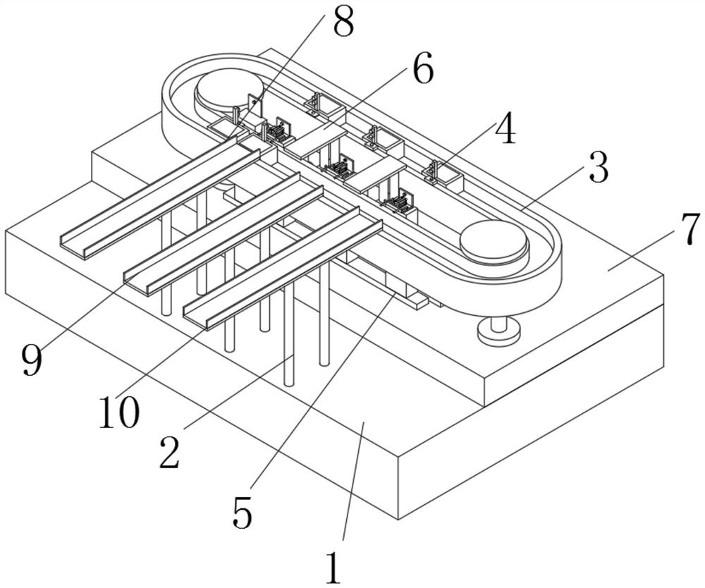
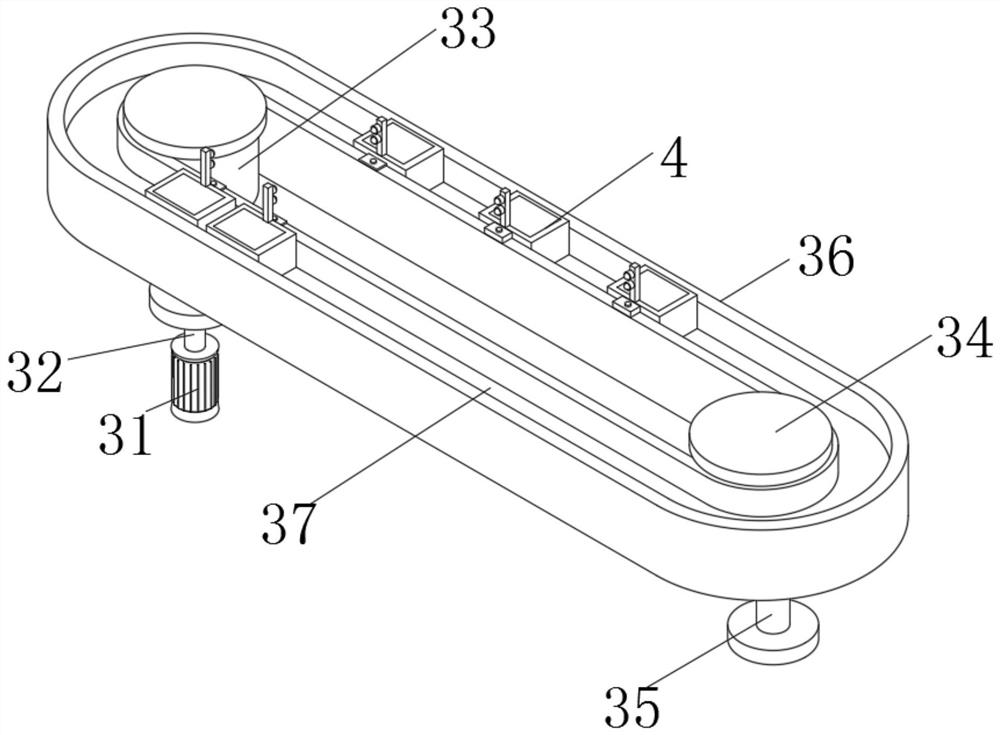
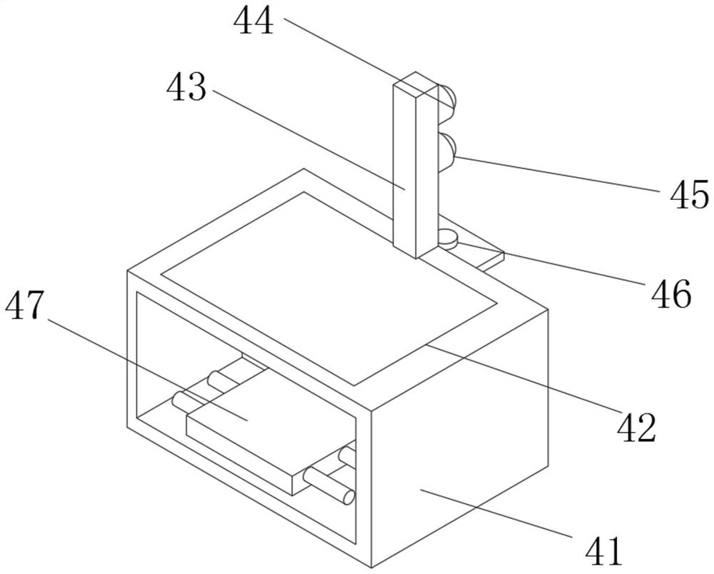

Image

  • Novel medical annular conveying line device
  • Novel medical annular conveying line device
  • Novel medical annular conveying line device

Examples


Embodiment Construction

[0026] In order to make the technical means, creative features, goals and effects achieved by the present invention easy to understand, the present invention will be further described below in conjunction with specific embodiments.

[0027] In the description of the present invention, it should be noted that the terms "upper", "lower", "inner", "outer", "front end", "rear end", "both ends", "one end", "another end" The orientation or positional relationship indicated by etc. is based on the orientation or positional relationship shown in the drawings, and is only for the convenience of describing the present invention and simplifying the description, rather than indicating or implying that the referred device or element must have a specific orientation, use a specific Azimuth configuration and operation, therefore, should not be construed as limiting the invention. In addition, the terms "first" and "second" are used for descriptive purposes only, and should not be understood ...


PUM


Abstract

The invention discloses a novel medical annular conveying line device which comprises a machine box. A chassis is fixedly installed at the right side of the upper end of the machine box, a conveying mechanism is arranged at the upper end of the chassis, the lower end of the conveying mechanism sequentially penetrates through the rear portion of the chassis and the rear portion of the upper end of the machine box and extends into the machine box, and three sets of supporting rods are fixedly installed on the left portion of the upper end of the machine box; and a first discharging channel, a second discharging channel and a third discharging channel are fixedly installed at the upper ends of the three sets of supporting rods correspondingly, the first discharging channel is located behind the second discharging channel, the second discharging channel is located behind the third discharging channel, and the first discharging channel, the second discharging channel and the third discharging channel are obliquely distributed in the manner that the left portions are low and the right portions are high. According to the novel medical annular conveying line device, the space utilization rate can be increased, the occupied area is further saved, classification operation of medical devices is achieved in the automatic discharging process, the conveying line function is more powerful, and the stability of conveying operation is guaranteed.

Description

technical field [0001] The invention relates to the technical field of medical delivery, in particular to a novel medical loop delivery line device. Background technique [0002] The conveying line is mainly to complete the conveying task of its materials. The traditional conveyor line is equipped with a conveyor chain consisting of many belt conveyors, roller conveyors, etc. around the warehouse, production workshop and packaging workshop. There are and path fork devices, elevators and ground conveying lines at the entrance and exit of materials. This type of transmission line is also widely used in the field of medical devices, but there are often effective problems in the transportation process of this type of transmission line: 1. The existing transmission line occupies a large area, and the utilization rate of space is not high; 2. The existing transmission line The line only has the function of conveying and does not have the function of automatic unloading, and it c...

Claims


Application Information

Patent Timeline
Patent Type & Authority Applications(China)
IPC IPC(8): B65G35/00B65G43/08B65G15/60B65G47/24B65G23/04B65G47/74
CPCB65G35/00B65G43/08B65G15/60B65G47/24B65G23/04B65G47/74B65G2201/02
Inventor 陈鑫
Owner 爱在工匠智能科技(苏州)有限公司
Why Eureka
Try Eureka