A Non-Uniform Inner Angle Structural Liquid Reservoir

A non-uniform and structured technology, applied in the field of spacecraft thermal control, can solve the problems that the capillary pore size cannot meet the requirements of continuous fluid supply, cannot meet the requirements of transport fluid velocity and flow rate, and the arrangement of porous media capillary structure is not unified. , to achieve the effect of enhancing capillary driving force, good encapsulation, and small flow resistance

Active Publication Date: 2021-06-11
CHINA ACADEMY OF SPACE TECHNOLOGY
View PDF0 Cites 0 Cited by
  • Summary
  • Abstract
  • Description
  • Claims
  • Application Information

AI Technical Summary

Problems solved by technology

[0003] In order to meet the above requirements, some internal structures need to be designed in the reservoir. Adding capillary porous media is a commonly used method at present. However, the type and size of porous media are determined by the capillary driving force provided by it and the corresponding resistance relationship: the capillary pore diameter is too large. If the pore size is too large, it cannot meet the requirements of continuous fluid supply, and if the pore size is too small, it will cause excessive flow resistance, which cannot meet the requirements of transport fluid velocity and flow rate.
At the same time, there is currently no unified criterion for the layout of the capillary structure of porous media. The liquid supply channel and the exhaust channel are only realized by different layout spaces.

Method used


Image

  • A Non-Uniform Inner Angle Structural Liquid Reservoir
  • A Non-Uniform Inner Angle Structural Liquid Reservoir
  • A Non-Uniform Inner Angle Structural Liquid Reservoir

Examples


Embodiment Construction

[0041] In order to make the object, technical solution and advantages of the present invention clearer, the embodiments disclosed by the present invention will be further described in detail below in conjunction with the accompanying drawings.

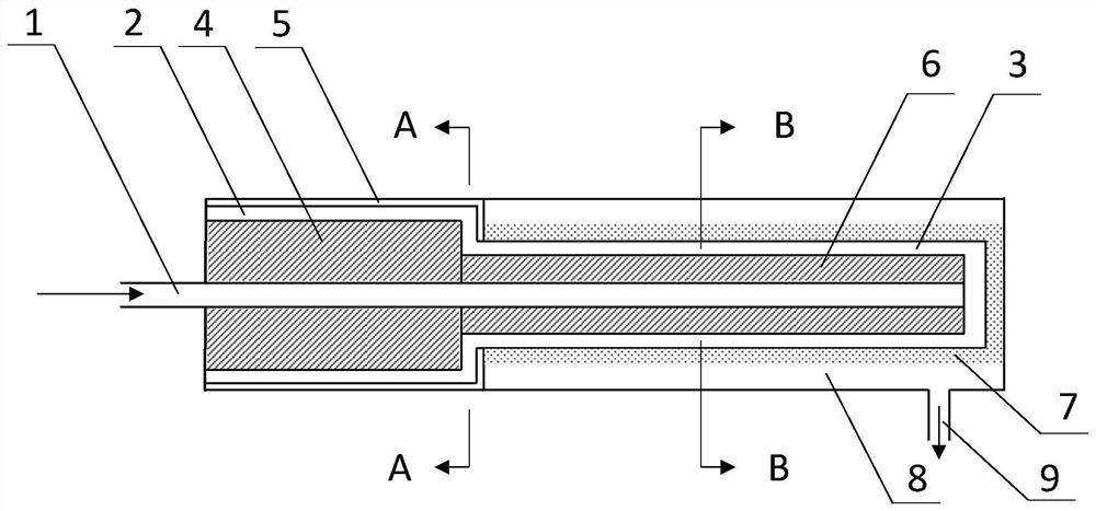
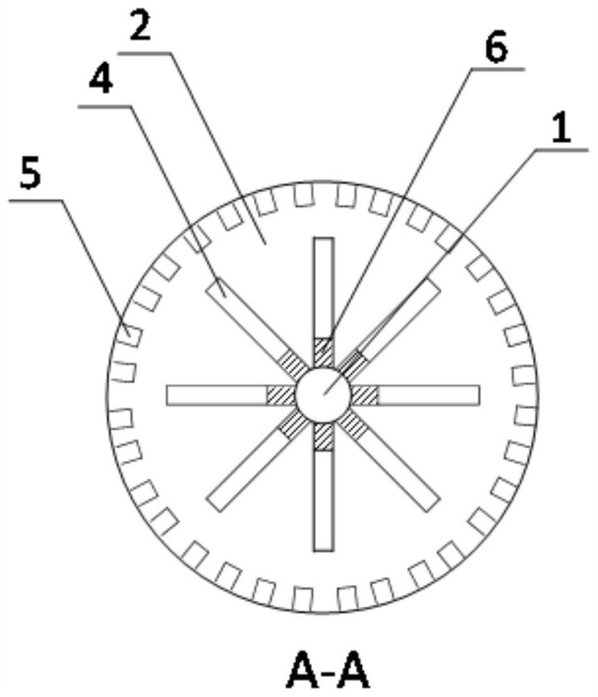
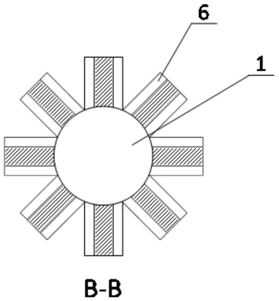
[0042] Such as Figure 1~3 , in this embodiment, the non-uniform internal angle structure liquid reservoir includes: liquid pipeline 1, main liquid storage chamber 2, auxiliary liquid storage chamber 3, primary internal angle structure 4, micro groove structure 5 and secondary internal angle structure 6. Among them, the main liquid storage chamber 2 and the auxiliary liquid storage chamber 3 are coaxial through chambers with unequal cross-sectional areas; the liquid pipeline 1 passes through the main liquid storage chamber 2 and reaches the farthest end of the auxiliary liquid storage chamber 3; The inner angle structure 4 is arranged in the main liquid storage chamber 2, and the secondary inner angle structure 6 is arranged in the au...


PUM


Abstract

The invention discloses a non-uniform interior angle structure liquid storage device, which comprises: a liquid pipeline, a main liquid storage chamber, an auxiliary liquid storage chamber, a first-level inner angle structure, a micro-groove structure and a second-level inner angle structure; the main liquid storage room and the auxiliary liquid storage room The liquid storage chamber is a coaxial through chamber with unequal cross-sectional area; the liquid pipeline passes through the main liquid storage chamber to reach the farthest end of the auxiliary liquid storage chamber; the first-level inner angle structure is set in the main liquid storage room, the second-level inner angle structure It is arranged in the auxiliary liquid storage chamber; wherein, the first-level inner angle structure is coaxial with the second-level inner angle structure, and is connected at the front end of the inlet of the auxiliary liquid storage room; the micro-groove structure is arranged along the inner wall of the main liquid storage room and extends to the auxiliary liquid storage room. The inlet of the liquid storage chamber communicates with the auxiliary liquid storage chamber. The invention has the advantages of simple structure, small flow resistance and directional and rapid steam exhaust capability. Even under the condition of anti-gravity, the capillary driving force provided by the inner angle structure makes the fluid working medium fill the auxiliary liquid storage chamber, ensuring that the loop heat pipe is in the condition of variable gravity. safe operation under conditions.

Description

technical field [0001] The invention belongs to the technical field of spacecraft thermal control, and in particular relates to a non-uniform internal angle structural liquid reservoir. Background technique [0002] The liquid receiver is an important component of the loop heat pipe. It is connected with the evaporator as a whole, collects the condensed liquid working medium, and continuously supplies the fluid working medium to the capillary core in the evaporator. The surface of the porous structure capillary core in contact with the heat source is used as the evaporation surface, and the two-phase interface forms a meniscus in the capillary pores, providing the capillary driving force to drive the circulation of the working fluid. In order to ensure the normal operation of the reservoir, it is required to have a continuous inner corner or capillary structure in the reservoir to realize continuous circulation and uninterrupted supply of working fluid. On the one hand, it ...

Claims


Application Information

Patent Timeline
Patent Type & Authority Patents(China)
IPC IPC(8): B64G1/50F28D15/04
CPCB64G1/506F28D15/043
Inventor 王庆功欧阳毅姚伟
Owner CHINA ACADEMY OF SPACE TECHNOLOGY
Why Eureka
Try Eureka