Vacuum glass coating equipment

A technology of vacuum glass and coating equipment, applied in vacuum evaporation coating, sputtering coating, ion implantation coating and other directions, can solve the problems of uneven coating thickness and affecting the quality of glass coating, and achieve good coating quality and use Flexible and convenient effects

Active Publication Date: 2019-12-10
咸阳镭瑟奥普光电科技有限公司
View PDF7 Cites 2 Cited by
  • Summary
  • Abstract
  • Description
  • Claims
  • Application Information

AI Technical Summary

Problems solved by technology

[0004] After the glass is pressed by the pressure roller, it will produce local bending deformation, and the deformation will enter the coating roller before it is released. As a result, when the glass passes through the coating roller, the thickness of the coating will be uneven, which will affect the coating quality of the glass.

Method used


Image

  • Vacuum glass coating equipment
  • Vacuum glass coating equipment
  • Vacuum glass coating equipment

Examples


Embodiment 1

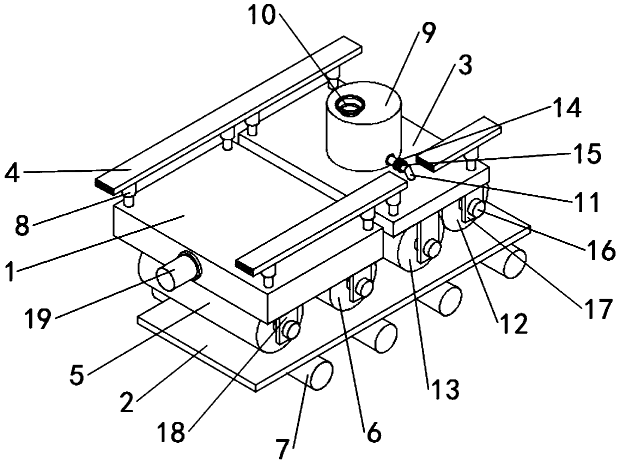
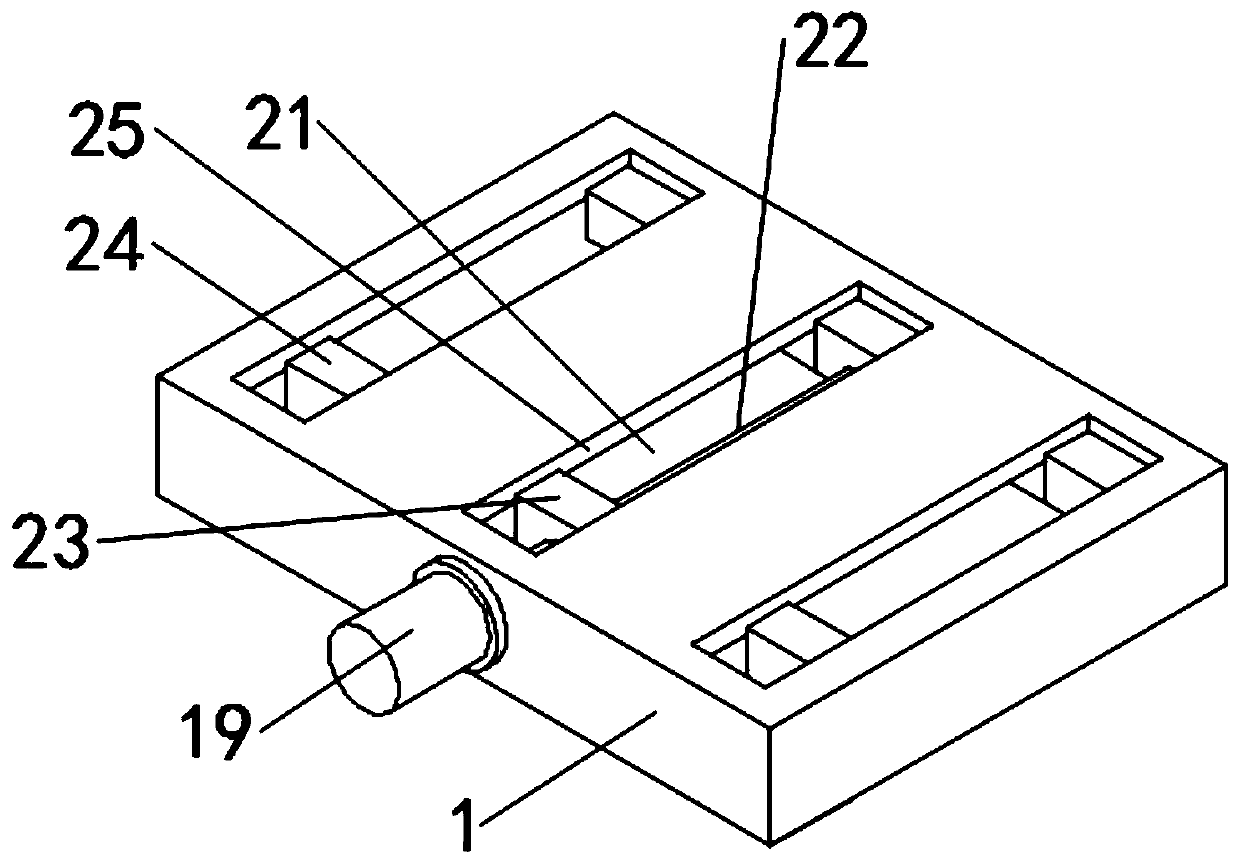
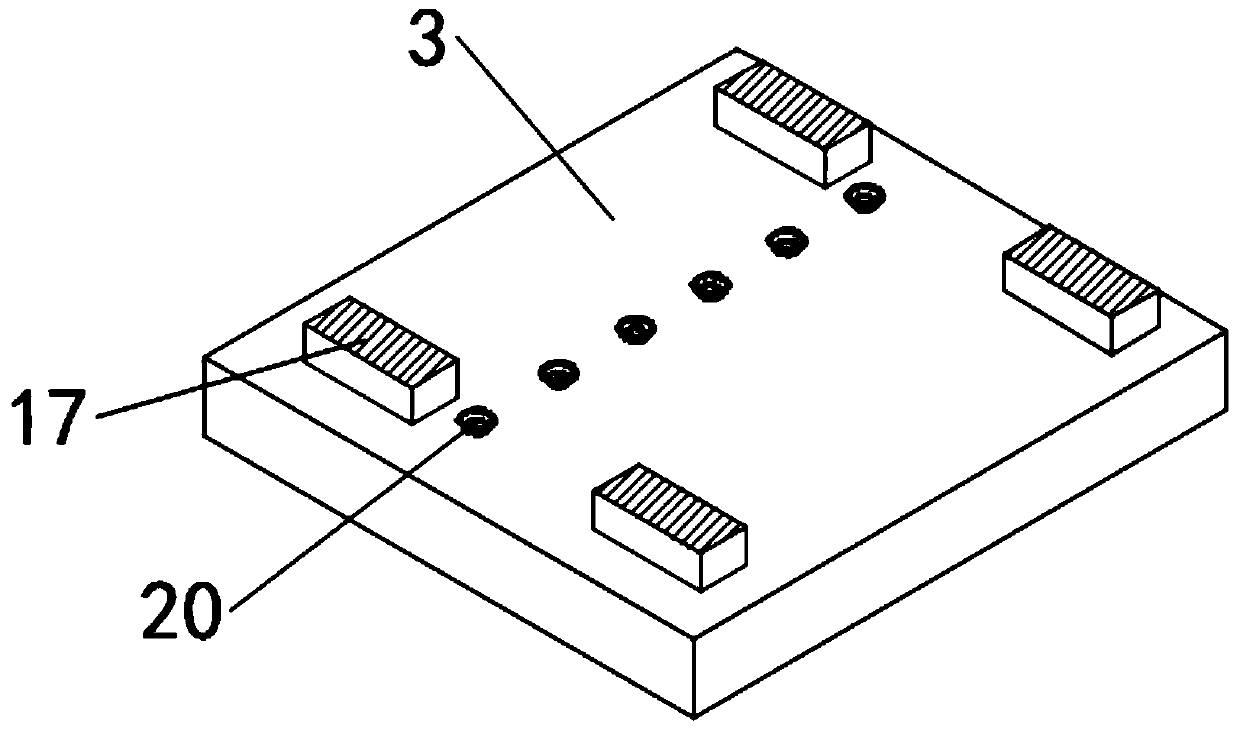
[0029] see Figure 1~3 , in an embodiment of the present invention, a vacuum glass coating device includes a support box 1, a support plate 3, a first pressing drum 5, a second pressing drum 6, a transmission roller 7, an electric push rod 8 and a liquid Cylinder 9;

[0030] Wherein, a plurality of said conveying rollers 7 that play a role in transporting and supporting the glass 2 are installed at the bottom of the frame 4, and the said support box 1 is mounted on the left side of the frame 4 in a lifting manner through the electric push rods 8 provided at its four corners. Upper part: an adjustment mechanism for adjusting the relative position between the first compression drum 5 and the second compression drum 6 is installed in the support box 1; the first compression drum 5 is adjusted by the adjustment mechanism The relative position between the second pressing drum 6 can adjust the first pressing drum 5 and the second pressing drum 6 to a suitable distance position acco...

Embodiment 2

[0039] see Figure 1~3 , in an embodiment of the present invention, a vacuum glass coating device includes a support box 1, a support plate 3, a first pressing drum 5, a second pressing drum 6, a transmission roller 7, an electric push rod 8 and a liquid Cylinder 9;

[0040] Wherein, a plurality of said conveying rollers 7 that play a role in transporting and supporting the glass 2 are installed at the bottom of the frame 4, and the said support box 1 is mounted on the left side of the frame 4 in a lifting manner through the electric push rods 8 provided at its four corners. Upper part: an adjustment mechanism for adjusting the relative position between the first compression drum 5 and the second compression drum 6 is installed in the support box 1; the first compression drum 5 is adjusted by the adjustment mechanism The relative position between the second pressing drum 6 can adjust the first pressing drum 5 and the second pressing drum 6 to a suitable distance position acco...


PUM


Abstract

The invention relates to the technical field of glass processing, in particular to vacuum glass coating equipment which comprises a supporting box, a supporting plate, a first compressing rotary drum,a second compressing rotary drum, conveying rollers, electric push rods and a hydraulic cylinder; the multiple conveying rollers, exerting the conveying and supporting effects to glass, are installedat the bottom of the rack; and the supporting box is installed on the upper part of the left side of a rack in a lifting manner through the electric push rods arranged at four corners of the supporting box and is internally provided with an adjusting mechanism used for adjusting the relative position between the first compressing rotary drum and the second compressing rotary drum. For the vacuumglass coating equipment provided by the invention, excessive deformation of the glass during coating can be avoided; and in addition, by adjusting the relative position between the two compressing rotary drums through the adjusting mechanism, the two compressing rotary drums can be adjusted to a proper distance position according to different glass toughness, and thus the effect of preventing deformation during compression of the glass is the best.

Description

technical field [0001] The invention relates to the technical field of glass processing, in particular to vacuum glass coating equipment. Background technique [0002] Coated glass is also called reflective glass. Coated glass is coated with one or more layers of metal, alloy or metal compound films on the surface of the glass to change the optical properties of the glass and meet certain specific requirements. The coated glass can be customized according to the different characteristics of the product. Divided into the following categories: heat reflective glass, low-emissivity glass, conductive film glass, etc. [0003] Most of the current glass coating equipment adopts the reverse roller coating method to achieve glass coating. That is to say, the glass passes through the conveying table and enters the pressure roller to press the glass head. The friction between the pressure roller and the glass is used to drive the glass to move forward and enter the coating roller. o...

Claims


Application Information

Patent Timeline
IPC IPC(8): C23C14/22C03C17/00
CPCC03C17/001C23C14/22
Inventor 齐锴亮
Owner 咸阳镭瑟奥普光电科技有限公司
Why Eureka
Try Eureka