
Centrifugal type stepless drive decelerating mechanism

A technology of infinitely variable speed and deceleration mechanism, used in clutches, mechanical equipment, one-way clutches, etc., can solve the problems of use, inability to have a wider application environment, and a fixed deceleration range, and achieve convenient use, simple structure, and fewer parts. The effect of loss

Pending Publication Date: 2019-12-10
无锡乐锡科技有限公司
View PDF0 Cites 0 Cited by
  • Summary
  • Abstract
  • Description
  • Claims
  • Application Information

AI Technical Summary

Problems solved by technology

[0002] At present, the deceleration mechanism on the market is a centrifugal friction type, but due to the fixed brake wheel, its deceleration range is also fixed, so it cannot be used in a wider application environment

Method used


Image

  • Centrifugal type stepless drive decelerating mechanism
  • Centrifugal type stepless drive decelerating mechanism
  • Centrifugal type stepless drive decelerating mechanism

Examples


Embodiment Construction

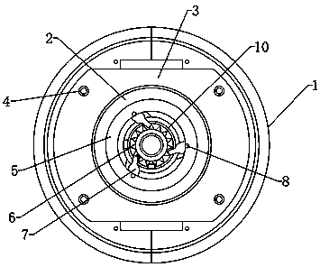
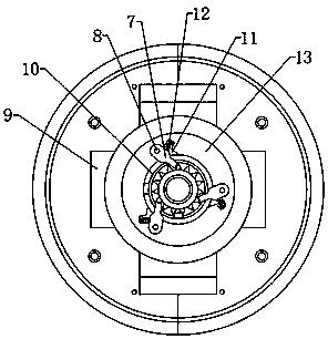
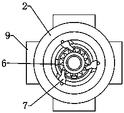
[0016] attached Figure 1-4 It is a specific embodiment of the present invention. The invention is a centrifugal infinitely variable speed reduction mechanism, which includes a reduction wheel assembly 1, a brake wheel body 2 and a one-way bearing 10. The brake wheel body 2 is provided with a plurality of limit splicing blocks 9, and the brake wheel body 2 passes through each The limit splicing block 9 and the speed reduction wheel assembly 1 are spliced ​​by connecting the main board 3, and the speed reduction wheel assembly 1 is provided with a groove consistent with the outer contour of the limit splicing block 9, and each speed reduction wheel assembly 1 utilizes the connecting bolt 4 to connect the main board 3. Connecting and splicing into a whole, a return tension spring 15 is installed between two adjacent reduction wheel assemblies 1, a limit gear 6 is provided on the one-way bearing 10 of the brake wheel body 2, and a limit gear 6 is arranged on the brake wheel body ...


PUM


Abstract

The invention belongs to the technical field of speed reducers, and particularly to a centrifugal type stepless drive decelerating mechanism. The centrifugal type stepless drive decelerating mechanismcomprises decelerating wheel assemblies, a brake wheel body and a one-way bearing, a plurality of limiting splicing blocks are arranged on the brake wheel body, the brake wheel body is spliced with the decelerating wheel assemblies through the limiting splicing blocks and a connecting main plate, grooves consistent with the limiting splicing blocks in external contour are formed in the decelerating wheel assemblies, the decelerating wheel assemblies and the connecting main plate are connected and spliced into a whole through connecting bolts, and a reset spring is assembled between the two adjacent decelerating wheel assemblies. The centrifugal type stepless drive decelerating mechanism has the advantages that the structure is simple, use is convenient, and component loss is reduced to the maximum extent by adopting the magnetic non-contact type design; the resistance can be automatically regulated according to the rotating speed, and operation is stable.

Description

technical field [0001] The invention belongs to the technical field of reducers, and in particular relates to a centrifugal infinitely variable speed reduction mechanism. Background technique [0002] At present, the deceleration mechanism on the market is centrifugal friction type, but due to the fixed brake wheel, its deceleration range is also fixed, so it cannot be used in a wider application environment. Contents of the invention [0003] In order to make up for the defects of the prior art, the present invention provides a centrifugal infinitely variable speed reduction mechanism. [0004] The present invention is achieved through the following technical solutions: [0005] A centrifugal infinitely variable speed reduction mechanism, including a reduction wheel assembly, a brake wheel body and a one-way bearing, the brake wheel body is provided with a plurality of limit splicing blocks, and the brake wheel body is connected to the speed reduction wheel assembly thro...

Claims


Application Information

Patent Timeline
Patent Type & Authority Applications(China)
IPC IPC(8): F16H15/02F16D41/12F16D27/00
CPCF16H15/02F16D41/12F16D27/00
Inventor 范胜
Owner 无锡乐锡科技有限公司
Learn More