High-frequency radar level meter capable of sweeping dust

A radar level meter and high-frequency technology, which is applied in the direction of engine lubrication, cleaning methods and tools, cleaning methods using tools, etc., can solve problems such as complex operation, hidden safety hazards in the cleaning process, frequent cleaning operation cycles, etc., to achieve Improved measurement accuracy and high strength

Inactive Publication Date: 2019-12-10
陕西诺盈自动化仪表有限公司
View PDF3 Cites 4 Cited by
  • Summary
  • Abstract
  • Description
  • Claims
  • Application Information

AI Technical Summary

Problems solved by technology

The current treatment method is to regularly check and clean the radar horn mouth and antenna attachments. There are problems such as frequent cleaning operation cycles, potential safety hazards in the cleaning process, and complicated operations.

Method used


Image

  • High-frequency radar level meter capable of sweeping dust
  • High-frequency radar level meter capable of sweeping dust

Examples


Embodiment 1

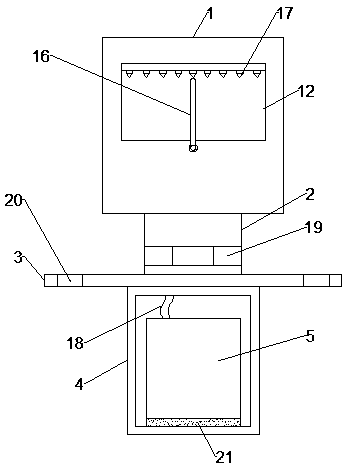
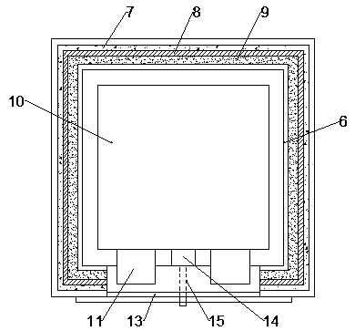
[0023] Such as Figure 1-2 As shown, the high-frequency radar level gauge according to the embodiment of the present invention includes an outer shell 1, the bottom end of the outer shell 1 is provided with a connecting body 2, and the bottom end of the connecting body 2 is provided with a flange 3, The bottom end of the flange 3 is provided with a box body 4, the inside of the box body 4 is provided with an air source 5, the inside of the outer casing 1 is provided with an inner casing 6, and the inner casing 6 is connected to the An anti-corrosion layer 7, a strength layer 8 and an anti-seismic filling layer 9 are sequentially arranged between the outer casing 1, and a radar level gauge body 10 is arranged inside the inner casing 6, and the radar level gauge body 10 One end is provided with a plurality of detection heads 11, and the outer casing 1 and the inner casing 6 are respectively provided with detection windows 12 on the sides close to the detection heads 11, and the ...

Embodiment 2

[0028] Such as Figure 1-2 As shown, the connecting body 2 and the flange 3 are connected through bolts 19, and the flange 3 is provided with a number of installation holes 20, and the connection between the air source 5 and the box 4 A buffer pad 21 is arranged between them, the rotation angle of the cleaning rod 16 is 270 degrees, the anti-corrosion layer 7 is made of epoxy resin, the strength layer 8 is made of carbon fiber, and the shock-resistant filling layer 9 is made of rubber.

[0029] From figure 1 It can be seen from the figure that the connecting body 2 and the flange 3 are connected through bolts 19, and the flange 3 is provided with a number of installation holes 20, and the gas source 5 and the box body 4 is provided with a buffer pad 21, the design of the bolt 19, the mounting hole 20 and the buffer pad 21 is relatively conventional, so no detailed description will be given.

[0030] In order to facilitate the understanding of the above-mentioned technical so...


PUM


Abstract

The invention discloses a high-frequency radar level meter capable of sweeping dust. The level meter comprises an outer shell; a connecting body is arranged at the bottom end of the outer shell; a flange plate is arranged at the bottom end of the connecting body; a box body is arranged at the bottom end of the flange plate; an air source is arranged in the box body; an inner shell is arranged in the outer shell; an anti-corrosion layer, a strength layer and an anti-seismic filling layer are arranged between the inner shell and the outer shell; a radar level meter body is arranged in the innershell; a plurality of detection heads are arranged at one end of the radar level meter body; a detection window is arranged on one side of the outer shell, a glass baffle is arranged in the detectionwindow, a motor is arranged at the bottom end of one side in the inner shell, a rotating shaft is arranged on an output shaft of the motor, a sweeping rod is arranged at the other end of the rotatingshaft, and an air nozzle is arranged on one side of the outer shell. The beneficial effects are that the detection window can be cleaned, the measurement precision is improved, and the level meter hasthe characteristics of corrosion resistance, shock resistance and high strength.

Description

technical field [0001] The invention relates to the technical field of radar level gauges, in particular to a high-frequency radar level gauge capable of cleaning dust. Background technique [0002] The radar level gauge is an integrated instrument, suitable for petroleum, chemical, cement and other production conditions, poor environmental conditions, flammable, explosive, toxic and harmful places. The radar level meter adopts microwave measurement technology, which has strong penetrating power, dust, steam and other factors will not affect the measurement, and has capabilities that other types of instruments do not have. However, there are some problems in the use of the radar level gauge measurement method in special environments. The level gauge is installed on the top of a closed container. When measuring an environment that is prone to dust, it is easy to accumulate dust on the probe, such as cement, coal etc. The current treatment method is to regularly check and cl...

Claims


Application Information

Patent Timeline
Patent Type & Authority Applications(China)
IPC IPC(8): G01F23/284B08B1/00B08B5/02
CPCB08B1/00B08B5/02G01F23/284
Inventor 刘姣
Owner 陕西诺盈自动化仪表有限公司
Why Eureka
Try Eureka