Dual-motor pressure generating system of weight loading mechanism

A technology of loading mechanism and dual motors, applied in the direction of measuring fluid pressure, measuring devices, instruments, etc., can solve the problems of poor reliability and stability, boring work, low degree of automation, etc., and achieve rapid and precise pressure building, accurate positioning and reliable effect

Pending Publication Date: 2019-12-10
DALIAN POLYTECHNIC UNIVERSITY
View PDF14 Cites 0 Cited by
  • Summary
  • Abstract
  • Description
  • Claims
  • Application Information

AI Technical Summary

Problems solved by technology

[0003] Piston pressure gauge is a common instrument for pressure gauge detection and calibration. The weight is generally the benchmark for piston pressure gauge pressure gauge detection and calibration. A specific weight is formed through a specific combination of weights, which is converted into liquid pressure by the hydraulic system and applied to the pressure gauge. , is the usual practice of pressure gauge detection, but the current piston pressure gauge, weight loading and unloading work, weight status determination and other work are generally done manually, the operator repeats the work, the work is boring, the degree of automation is low, and it is easy to produce verification. error, and manual operation is easily affected by factors such as operator's emotion and experience, and it is easy to damage the weight and related parts
That is to say, the weight loading method of the piston pressure gauge is mainly manual loading at present, and the weight placement depends on manual handling, which is time-consuming, labor-intensive, poor in reliability and stability, and an automated weighting process and device are necessary

Method used


Image

  • Dual-motor pressure generating system of weight loading mechanism
  • Dual-motor pressure generating system of weight loading mechanism
  • Dual-motor pressure generating system of weight loading mechanism

Examples


Embodiment Construction

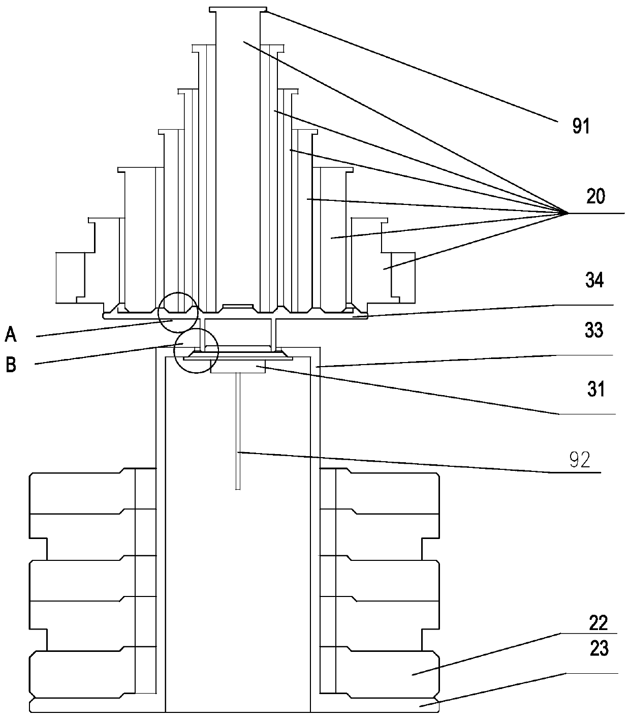
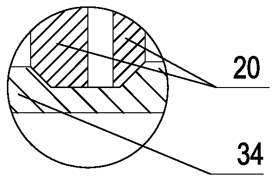
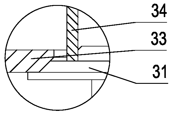
[0027] like Figure 1-7 . The combined weight loading mechanism shown in 9-11 includes a piston weight 31 connected to the lower piston rod 92 for weighing or pressure calibration; the upper part of the piston weight 31 is connected to the upper part of the cylindrical hanging basket weight 33 At the center of the barrel mouth; the outside of the bottom of the barrel wall of the hanging basket weight 33 is connected to a radial ring-shaped weight tray 23 , and the ring-shaped disc-shaped weights 22 are stacked on the weight tray 23 . The upper part of the piston weight 31 is also connected to a tray weight 34 above the hanging basket weight 33 through a connecting structure; a set of nested cylindrical weights 20 is arranged on the tray weight 34 . The disc weight 22 is provided with an independent disc weight loading and unloading unit. The cylindrical weight 20 is provided with an independent cylindrical weight loading and unloading unit. Wherein, the piston cylinder of th...


PUM


Abstract

The invention discloses a dual-motor pressure generating system of a weight loading mechanism, which comprises a piston cylinder (61) for generating pressure and a piston (60), and is characterized inthat the piston (60) is connected with a screw rod (57) and a screw rod sleeve (56); the screw sleeve is connected with a first servo motor (51); by means of a second servo motor and a first servo motor which are additionally arranged and connected with a transmission mechanism, control over a pumping executing mechanism of the preloading pump, an opening and closing action mechanism of the pressure release valve and an opening and closing action mechanism of the increasing valve is achieved. Specifically, the pressure output end of the piston cylinder is connected with a gauge connecting seat (77) of a pressure gauge (78) and a pressure release valve (74) in parallel. A pressure cavity in the rear portion of the pressure output end of the piston cylinder is connected with the output endof an increasing valve (73), and the oil supply end of the increasing valve is connected with an oil outlet of a pre-pressing pump (70). An oil inlet of the pre-pressing pump is connected with an oilcup (75). The two servo motors are adopted for controlling the pre-pressing pump and the pressure regulator to be matched to achieve pressure generation, the pre-pressing pump is used for conducting rapid pressurization in the initial stage of pressurization, the pressure regulator is adopted for conducting accurate pressurization after the pressure reaches a certain degree, and full-automatic, rapid and accurate pressure generation of the pressure is achieved.

Description

technical field [0001] The invention relates to an automatic weight adding device, and more specifically relates to the structural improvement of a piston pressure gauge. Background technique [0002] Pressure is one of the important process parameters in industrial production. In the field of pressure detection, it is often necessary to detect system pressure. Various forms of pressure gauges, pressure sensors, and pressure transmitters are commonly used instruments for pressure detection. , aerospace, automobile, power generation, medium transmission, water supply and gas supply, etc. in almost all fluid-related fields. The performance of the pressure gauge is directly related to the quality of the test results. In order to ensure the detection accuracy of the instrument, the pressure gauge must be calibrated regularly. If the pressure detection is inaccurate, it will not only affect the production efficiency, reduce the product quality, but even cause serious safety acci...

Claims


Application Information

Patent Timeline
Patent Type & Authority Applications(China)
IPC IPC(8): G01L27/00
CPCG01L27/005
Inventor 高腾庞桂兵卜繁岭
Owner DALIAN POLYTECHNIC UNIVERSITY
Why Eureka
Try Eureka