Condensation sensor, condensation detection device prepared by using the condensation sensor, and detection method

A detection device and detection method technology, applied in the field of sensors, can solve the problems of low early warning accuracy, reduced accuracy and influence of capacitive sensors, and achieve the effects of high reliability, improved service life and high economic benefits

Active Publication Date: 2019-12-10
安徽帕维尔智能技术有限公司
View PDF9 Cites 3 Cited by
  • Summary
  • Abstract
  • Description
  • Claims
  • Application Information

AI Technical Summary

Problems solved by technology

[0003] Condensation detectors in the prior art mainly include three types: the first is the temperature and humidity sensor, which performs statistics and calculations based on temperature and humidity data to predict the risk of condensation, thereby providing early warning of condensation; The disadvantage of this technology is that the condensation condition is not only affected by temperature and humidity conditions; it is also affected by the particle content in the air, the detection accuracy of the sensor, and other environmental factors, so the accuracy of this prediction is relatively reduced
[0006] However, during the detection process of capacitive sensors, the change of detection capacitance mainly depends on the total volume of droplets between parallel electrodes, rather than the size of individual droplets; if the air humidity is high, abundant small droplets can be formed, then even Small droplets fail to form drippable droplets, and capacitive sensors also give early warning, resulting in false positives
Therefore, the early warning accuracy of capacitive sensors for equipment condensation is relatively low.

Method used


Image

  • Condensation sensor, condensation detection device prepared by using the condensation sensor, and detection method
  • Condensation sensor, condensation detection device prepared by using the condensation sensor, and detection method
  • Condensation sensor, condensation detection device prepared by using the condensation sensor, and detection method

Examples


Embodiment Construction

[0031] To make the objectives, technical solutions, and advantages of the embodiments of the present invention clearer, the technical solutions in the embodiments of the present invention will be described clearly and completely in conjunction with the accompanying drawings in the embodiments of the present invention.

[0032] In the description of the present invention, it should be noted that, unless otherwise stated, "a plurality" means two or more; the terms "upper", "lower", "left", "right", and "internal" "," "outer", "front end", "rear end", "top", "bottom", etc. indicate the orientation or positional relationship based on the orientation or positional relationship shown in the drawings, only for the convenience of describing the present invention and simplifying The description does not indicate or imply that the pointed device or element must have a specific orientation, be configured and operated in a specific orientation, and therefore cannot be understood as a limitati...


PUM

PropertyMeasurementUnit
critical dimensionaaaaaaaaaa

Abstract

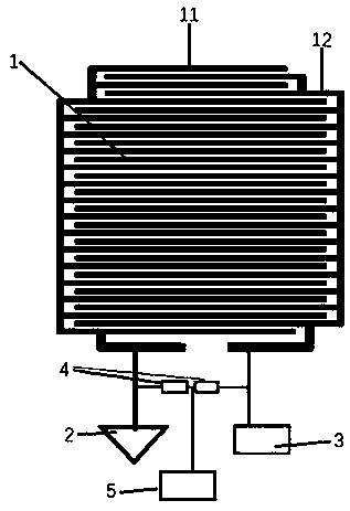
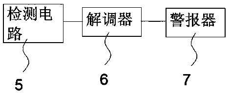
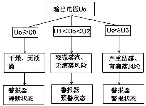
The invention belongs to the technical field of sensors, and particularly relates to a condensation sensor, a condensation detection device prepared by using the condensation sensor, and a detection method. The condensation sensor comprises a detection electrode pair, wherein the detection electrode pair is composed of a first electrode set and a second electrode set, the first electrode set and the second electrode set comprise a plurality of parallel electrodes arranged in a comb tooth shape, the parallel electrodes in the first electrode set and the second electrode set are arranged in a staggered mode, the adjacent parallel electrodes are arranged at equal intervals, and the interval is smaller than 2 mm. The first electrode set is grounded, and the end part of the second electrode setis connected with a radio frequency transmitting circuit; two detection resistors which are connected in series are electrically connected between the first electrode set and the second electrode set, the middle point of the two detection resistors is used as an output point, and the detection circuit detects the voltage value of the output point and judges the condensation condition of the equipment according to the voltage value. The detection device prepared by using the condensation sensor has the advantages of high precision, a low false alarm rate and high reliability.

Description

Technical field [0001] The invention belongs to the technical field of sensors, and specifically relates to a condensation sensor and a condensation detection device and a detection method prepared therefor. Background technique [0002] In the power system, various switch cabinets, compensation cabinets and other cabinet-type equipment are used in large quantities, and these cabinet-type equipment are used in complex environments. Condensation may form inside the device when the humidity is high; according to calculations, when the size of the droplets produced by condensation is greater than 2mm, the droplets may drip, and the dripping droplets may cause a short circuit to the device Other electrical safety incidents affect the normal operation of the power system. In order to solve this problem, technicians use various detection elements to predict the condensation of the equipment, and combine the dehumidification system to dehumidify the inside of the equipment to reduce th...

Claims


Application Information

Patent Timeline
Patent Type & Authority Applications(China)
IPC IPC(8): G01N27/00G01N15/02
CPCG01N15/02G01N27/00
Inventor 路巍李培安阮法杜广君
Owner 安徽帕维尔智能技术有限公司
Why Eureka
Try Eureka