Split type three-phase three-wire high-voltage electric energy metering box

A three-phase three-wire, high-voltage electric energy technology, applied in the direction of measuring electrical variables, measuring devices, electrical components, etc., can solve the problems of inconvenient replacement and installation, inconvenient installation, scrapping of metering boxes, etc., achieve less replacement equipment and reduce varieties , The effect of saving the cost of spare parts

Pending Publication Date: 2019-12-10
陈劲游
View PDF1 Cites 1 Cited by
  • Summary
  • Abstract
  • Description
  • Claims
  • Application Information

AI Technical Summary

Problems solved by technology

[0002] Electric energy metering is the basis for the economic calculation and calculation of electricity charges in all links of the power grid. The three-phase three-wire high-voltage electric energy metering box is a high-voltage metering device that is widely used in 6kV ~ 10kV high-voltage power grids. It is generally composed of two voltage transformers and two Two current transformers are combined and packaged into one body, so they have the characteristics of compact structure. However, since the invention, when one of the four transformers is damaged, the entire metering box will be completely scrapped, resulting in waste. The equipment is still relatively heavy, and it is inconvenient to install on the outdoor stand and column.
[0003] For example, the Chinese invention patent "An outdoor two-element three-phase power metering box with protection publication number is CN108535525A, application date: July 5, 2018", although the product and related electrical equipment can be protected by installing a fuse, but there is no It can solve the problems of overall replacement and inconvenient installation after failure

Method used


Image

  • Split type three-phase three-wire high-voltage electric energy metering box
  • Split type three-phase three-wire high-voltage electric energy metering box
  • Split type three-phase three-wire high-voltage electric energy metering box

Examples


Embodiment Construction

[0023] In order to make the object, technical solution and advantages of the present invention more clear, the implementation manner of the present invention will be further described in detail below in conjunction with the accompanying drawings and embodiments. It should be understood that the specific embodiments described here are only used to explain the present invention, but not to limit the present invention.

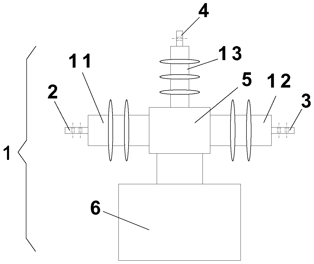
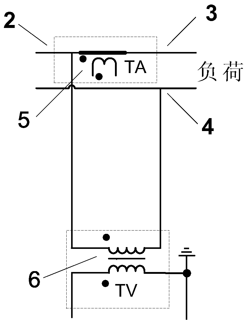
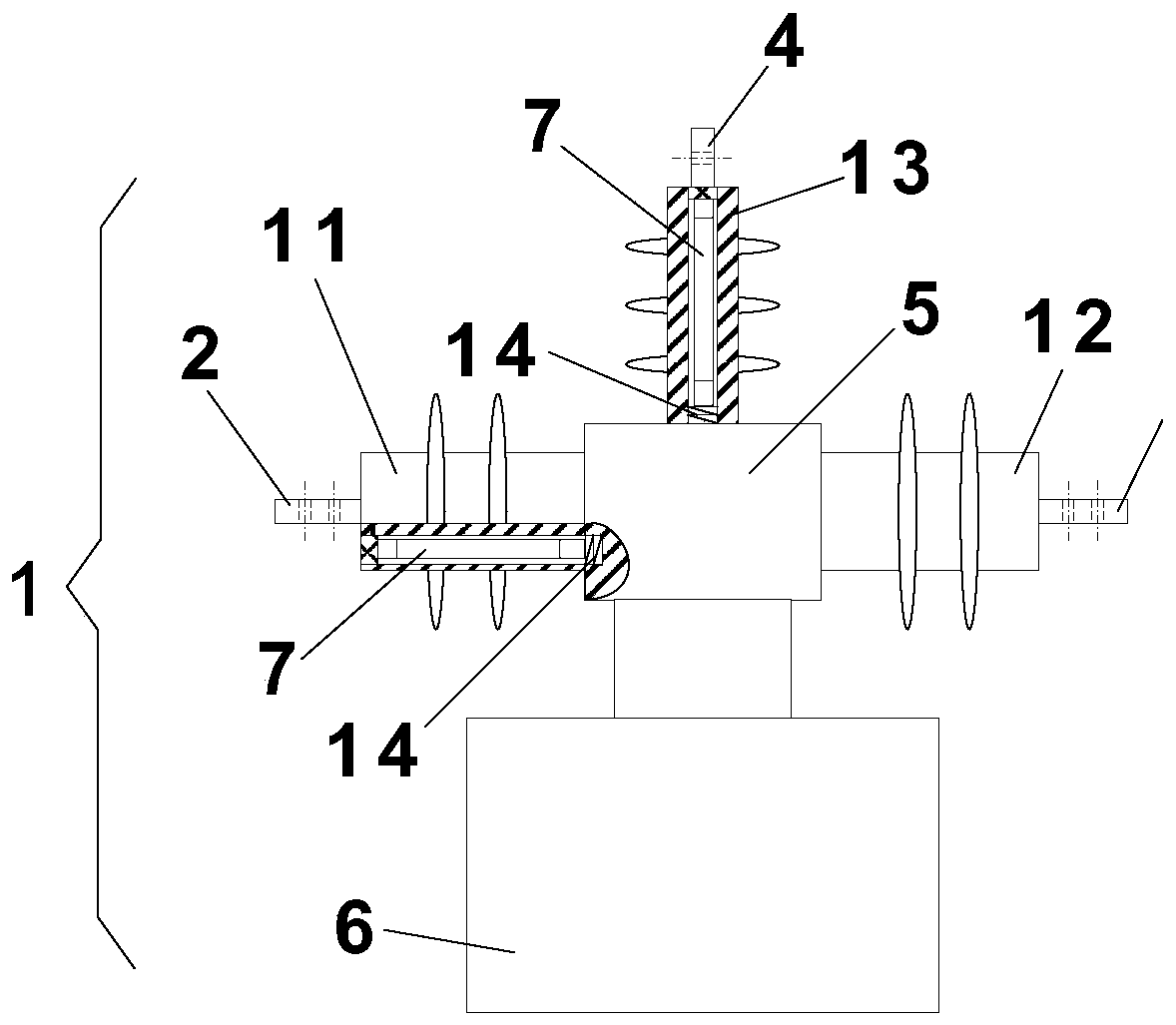
[0024] Such as figure 1 , figure 2 As shown, it is a single-phase combined transformer 1 structure. The single-phase combined transformer 1 includes a power supply terminal 2 connected to a high-voltage grid power supply, a load terminal 3, and a B-phase voltage terminal 4. The single-phase combined transformer 1 includes A single-phase current transformer 5 and a single-phase voltage transformer 6 are provided. The two ends of the primary side of the single-phase current transformer 5 are respectively connected to the power supply terminal 2 and the load termi...


PUM


Abstract

The invention discloses a split type three-phase three-wire high-voltage electric energy metering box that comprises two single-phase combined transformers; the single-phase combined mutual inductor comprises a power supply end, a load end and a B-phase voltage end which are connected with a high-voltage power grid. The two single-phase combined transformers are independently packaged and can be interchanged; when the two single-phase combined transformers are exchanged, the connection directions of the power supply end, the load end and the B-phase voltage end and leads of the power supply, the load and a B-phase line of the high-voltage power grid are unchanged; the two B-phase voltage ends are still connected with the B-phase line of the high-voltage power grid through the lead betweenthe two single-phase combined transformers; the three-phase three-wire high-voltage electric energy metering box is formed by combining two independently packaged single-phase combined transformer single bodies with the same appearance structure and internal connection, so that electric energy metering is realized, the weight of the mounting single body of the metering box is greatly reduced, andthe mounting is light and convenient.

Description

[technical field] [0001] The invention relates to measuring instruments and meters, in particular to a split-type three-phase three-wire high-voltage electric energy metering box. [Background technique] [0002] Electric energy metering is the basis for the economic calculation and calculation of electricity charges in all links of the power grid. The three-phase three-wire high-voltage electric energy metering box is a high-voltage metering device that is widely used in 6kV ~ 10kV high-voltage power grids. It is generally composed of two voltage transformers and two Two current transformers are combined and packaged into one body, so they have the characteristics of compact structure. However, since the invention, when one of the four transformers is damaged, the entire metering box will be completely scrapped, resulting in waste. At that time, the equipment was still relatively heavy, and it was inconvenient to install on outdoor stands and columns. [0003] For example, ...

Claims


Application Information

Patent Timeline
Patent Type & Authority Applications(China)
IPC IPC(8): G01R11/04G01R11/02H01F27/40H02H7/26
CPCG01R11/02G01R11/04H01F27/40H02H7/26
Inventor 陈劲游陈通
Owner 陈劲游
Why Eureka
Try Eureka