Control circuit of medical nutrient solution heater
A technology for controlling circuits and heaters, applied in the field of medical devices, can solve problems such as overheating of nutrient solution and invisible temperature, and achieve the effects of reducing diarrhea, reducing cold stimulation, and reducing discomfort
- Summary
- Abstract
- Description
- Claims
- Application Information
AI Technical Summary
Problems solved by technology
Method used
Image
Examples
Embodiment 1
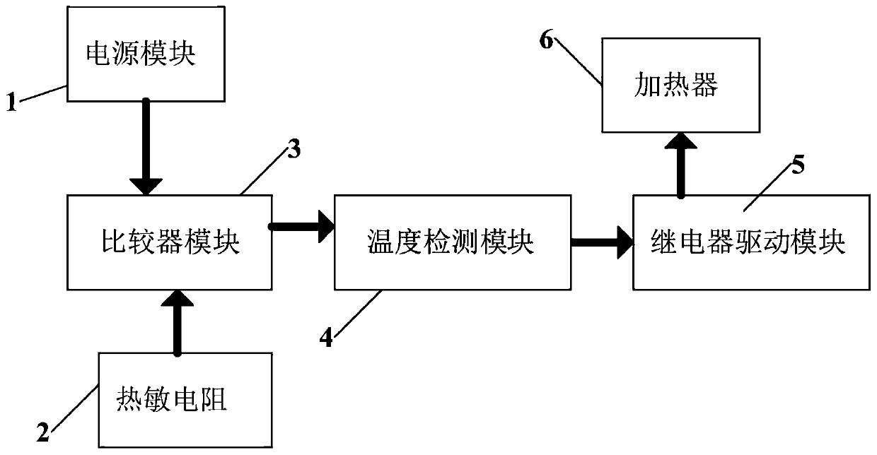
[0015] A medical nutrient solution heater control circuit, such as figure 1 As shown, it includes a power supply module 1, a thermistor 2, a comparator module 3, a temperature detection module 4, a relay drive module 5 and a heater 6, and the output end of the thermistor 2 is connected to the input of the comparator module 3 end, the output end of the comparator module 3 is connected to the input end of the temperature detection module 4, the output end of the temperature detection module 4 is connected to the input end of the relay drive module 5, and the comparator module 3 is used to control the relay The drive module 5 works, and the output end of the relay drive module 5 is connected to a heater 6, and the heater 6 is used to heat the nutrient solution. The power module 1 is a thermistor 2, a comparator module 3, a temperature detection Module 4, relay driver module 5 and heater 6 supply power.
[0016] After the heater 6 control circuit is powered on and the upper and l...
Embodiment 2
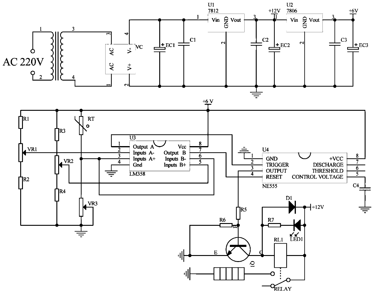
[0018] A medical nutrient solution heater control circuit, such as figure 2 As shown, the comparator module 3 includes a thermistor 2, resistors R1~R4, potentiometers VR1~VR3, and LM358, one end of the resistor R1 is connected to the power module 1+6V, and the other end of the resistor R1 is connected to the potentiometer One end of VR1 is connected, the Inputs A-pin of the operational amplifier LM358 is connected to the output terminal of the potentiometer VR1, one end of the resistor R2 is connected to the other end of the potentiometer VR1, the other end of the resistor R2 is grounded, and the Gnd of the operational amplifier LM358 The pin is grounded, one end of the resistor R3 is connected to the power module 1+6V, the other end of the resistor R2 is connected to the potentiometer VR2, the Inputs B+ pin of the operational amplifier LM358 is connected to the output terminal of the potentiometer VR2, and the resistor One end of R4 is connected to the other end of the poten...
PUM
 Abstract
Description
Claims
Application Information
 - R&D
- Intellectual Property
- Life Sciences
- Materials
- Tech Scout
- Unparalleled Data Quality
- Higher Quality Content
- 60% Fewer Hallucinations
Browse by: Latest US Patents, China's latest patents, Technical Efficacy Thesaurus, Application Domain, Technology Topic, Popular Technical Reports.
© 2025 PatSnap. All rights reserved.Legal|Privacy policy|Modern Slavery Act Transparency Statement|Sitemap|About US| Contact US: help@patsnap.com


